Aircraft stabilization with Pictorus
In this blog post we're going to illustrate how to develop, deploy, and test a simple stabilization controller for a small, remotely piloted fixed-wing aircraft using Pictorus. All the hardware involved is relatively cheap and available on Amazon, and the software development and deployment is free as part of our ongoing Open Beta.
Remote Control Background
Typically, an RC-controlled aircraft relies on stick input from a remote control transmitter such as the FlySky FS-i6s to actuate the elevator, ailerons, rudder, and/or other control surfaces directly, in addition to commanding motor throttle. This can be quite a difficult way to fly for inexperienced pilots, because raw servo commands require constant, minute adjustments to compensate for wind disturbances. The problem is exacerbated since the pilot is often observing the aircraft from long range, at odd angles, and is unable to feel disturbances the way an onboard pilot can. Without proper correction, or if the pilot over-corrects, the aircraft can easily stall, or aggressively roll or pitch into an uncontrollable state – often leading to "rapid disassembly events", as they like to say.
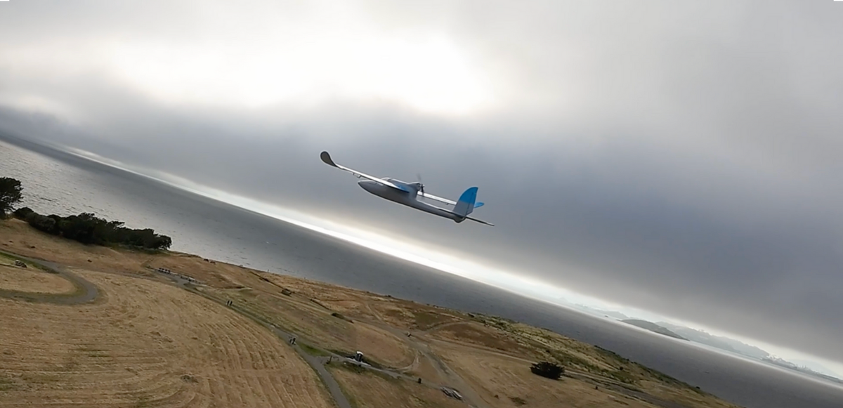
Over-correction leads to near-rapid disassembly event!
Autopilot To The Rescue!
To make things easier, various levels of autopilot functionality can be introduced by an onboard flight computer. For example, we're going to demonstrate some relatively simple roll and pitch angle control. This means the stick positions commanded by the pilot will be interpreted by the aircraft as desired roll and pitch angles with respect to the Earth's surface. So, if the pilot is holding the roll stick at a fixed 10 degrees, the aircraft will adjust ailerons until the aircraft actually achieves a 10 degree roll angle with respect to the ground, and then make small real-time adjustments to maintain it in the presence of disturbances. We'll do similar control for pitch angle. This should make piloting much easier - and we'll find out when we go fly!
For yaw, we'll introduce some light yaw-rate damping, meaning we'll have the autopilot attempt to lightly resist changes in yaw (heading). This means the autopilot will actually fight the pilot (slightly) when they first attempt to turn, but it also means it will be a lot easier to maintain a fixed heading for the majority of the flight when the pilot does not want to yaw.
A quick note - aeronautic afficiandos will point out that controlling angles with respect to the Earth's surface isn't really "proper" attitude control. What we really should be controlling are the angles flown with respect to the wind. This typically requires additional hardware to estimate the wind direction. We'll probably demonstrate this in future posts, but for now, under light winds (and non-acrobatic piloting) it often doesn't make a huge difference so we'll keep things simple. We should achieve a noticeable improvement in ease of control just by introducing Earth-relative angle control.
Cheap off-the-shelf sensors like the BNO085 IMU make it easy to do Earth-relative control, since the accelerometer always knows where "down" is (Earth's gravity vector), and the onboard magnetometer adds an additional sense of North. Coupled with gyroscopic angular measurements and the other 2 axes of acceleration, modern Kalman filter-powered IMUs like this one do a surprisingly good job of estimating orientation with respect to Earth, without any help from GPS.
We'll also eventually want to implement some other advanced autopilot features - altitude hold, cruise control, and GPS waypoints being typical next steps. Eventually, we could compose an autopilot that even returns to its takeoff position and loiters in a holding pattern.
Flight Control Via RaspberryPi - But Why?
As described above, there's clearly a lot of features we could choose to implement to make piloting easier and more fun, and this could eventually involve a lot of sensors and actuators, with all sort of power requirements and communication protocols. It's really easy to mess this up and fry your board, so a lot of fantastic flight control hardware (like the Pixhawk) have been developed by the RC community over years to help enthusiasts get flying easily and safely. These are mature hardware solutions with excellent electrical circuit protections, support a ton of external devices, and have a rich software ecosystem we could easily plug into if we wanted. In fact, they're so good, there are even commercial drone products that use these off-the-shelf aircraft controllers under the hood.
However, engineers developing new hardware products often have to start from scratch, for a variety of reasons. And for students learning the ropes of vehicle controls, rolling your own is still the best way to learn. That's why we're going to do this project entirely from a RaspberryPi Zero - a small, cheap single board computer with low power consumption (nearly on par with some embedded devices) and a Linux operating system.
But it's important to understand why hardened products like the Pixhawk exist: It's easy to electrically starve (or over-volt) your hardware (including the main control board) if you're not careful about power distribution. In fact, one of the joys of trying to develop your own flight controller is learning the hard way just how impressive what existing solutions have achieved.
This is all to say - tinker at your own risk! And be mindful of your surroundings, especially when trying to fly experimental hardware. It loves to fly away from you!
Flight Controller Design
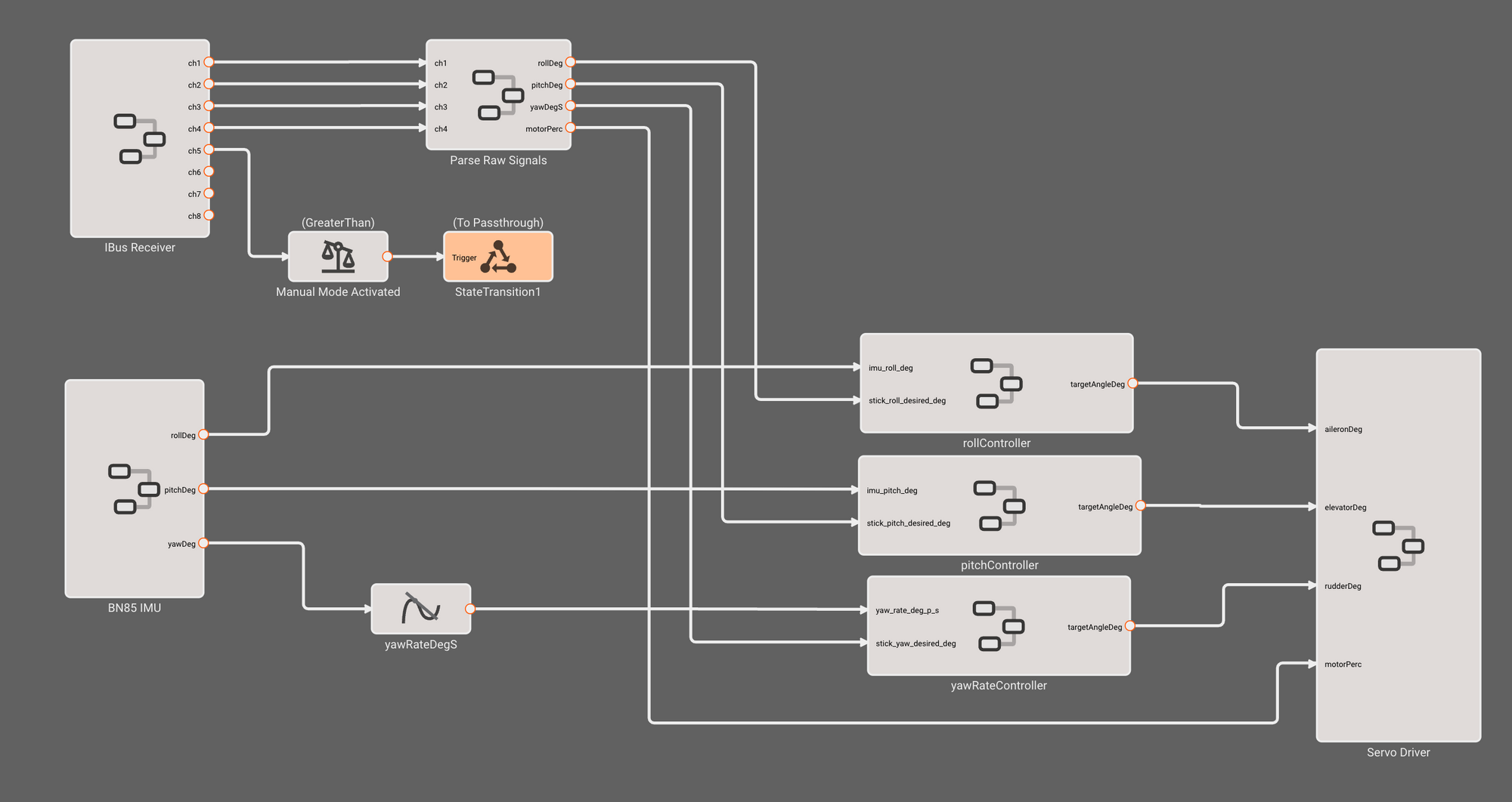
The top level diagram has each sensor/actuator organized into its own component, and three identical attitude controllers for roll, pitch, and yaw.
First we parse FkySky RC serial data from the IBus receiver, which gives us the current values of each stick position, in a digital range of 500-2000. Next, we pass that raw data into a component we've made to convert into desired angles in degrees (or angle rate in degrees/sec for yaw) that we can use in the attitude controllers.
Next, we use a BNO085 IMU API Component (available free in the public marketplace) to read roll, pitch, and yaw angles from the IMU. We pass those angles, along with the associated stick commands, into each of the three attitude controllers. Finally, we pass the servo commands we compute out to the servo driver.
Flight Control State Machine
We want to be able to disable our autopilot for debugging purposes (or if our pilot is feeling sporty) with the flip of a switch on the RC, so we need to introduce a simple State Machine for our flight controller. Pictorus's State Machine workflow makes it easy to describe our States and their transitions graphically:
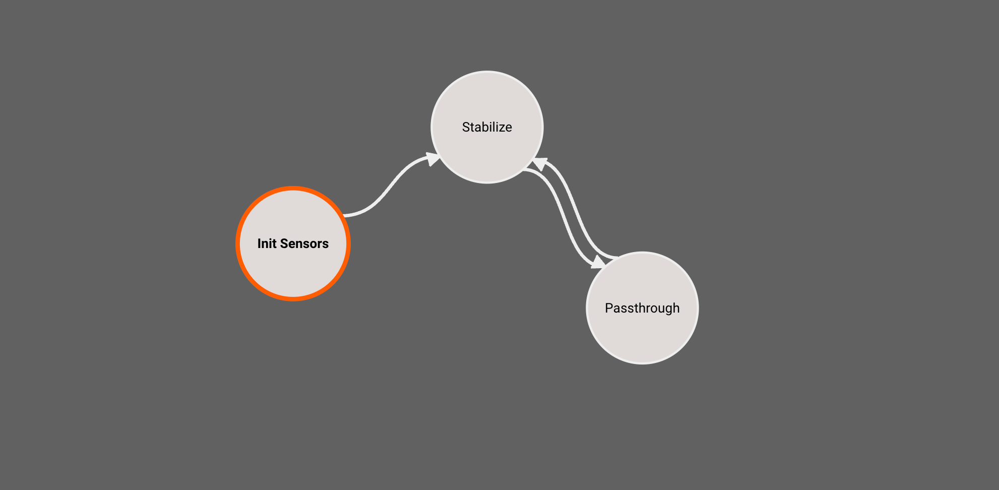
Our autopilot diagram resides in the Stabilize State, and Passthrough simply commands RC stick input directly to the servos. This gives us the same behavior as if our flight controller did not exist and the receiver was wired directly to servos.
We'll use RC channel 5, which corresponds to one of the aux switches on the transmitter, as the trigger for the state transition between Stabilize and Passthrough based on whether channel 5 is high (> 1500).
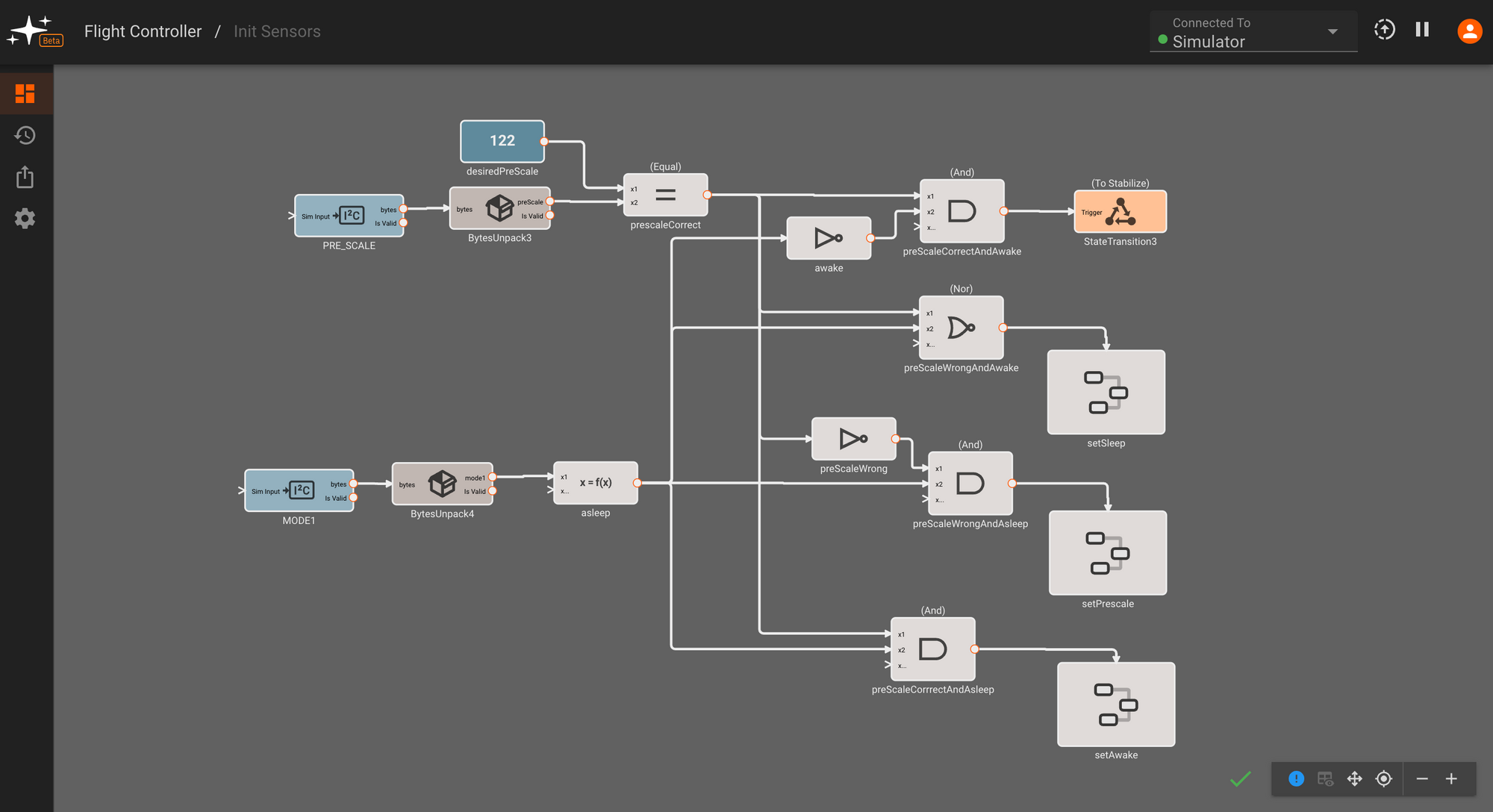
Finally, we need an Init Sensors state, which is entered by default (indicated by orange outline), to send some configuration commands to our servo driver.
Getting Stick Input Data From The Transmitter
(We've dedicated a blog post to this section, if you'd like more details)
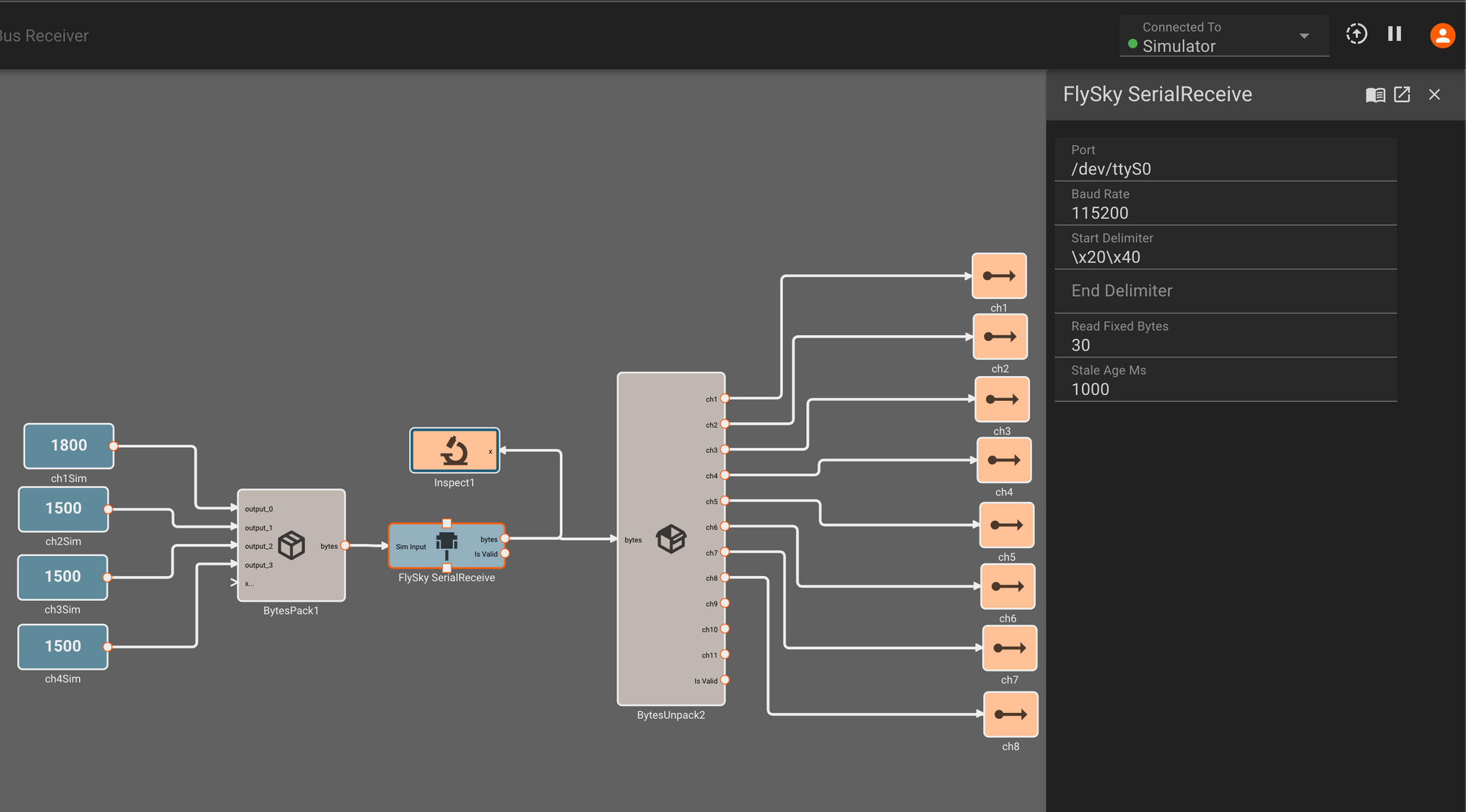
To read stick input, we need to use a SerialReceive block as shown below. Double-clicking on the block brings up its parameters, allowing us to specify the port address and baud rate of our device. We also describe the expected serial message, as defined in the transmitter data sheet: Starting with characters \x20\x40, and reading 30 bytes from there:
All data transmitted between computers are inherently bytes, which are meaningless to us until we define how the values we're expecting to read from this sensor are represented in byte form. We need to deserialize the data we're reading from the device into useful values for our controller.
To do this, we connect a BytesUnpack block to the SerialReceive block:
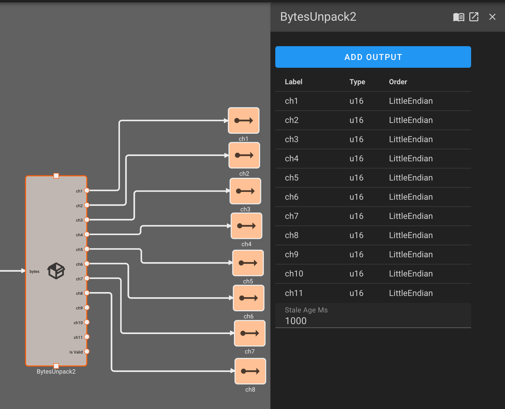
For our BytesUnpack block, we specify the data type (unsigned 16-bit integers) and Endian-ness of the individual signals packed into each 30 byte block of data we read over serial. Each of these channels represents a different stick or switch on the FlySky transmitter.
The FlySky receiver component we've just reviewed is publicly available to all users via our Component Marketplace. So if you've got one of these at home and want to experiment with it, you can add this Component to your library and simply drop it into a new app.
Getting Roll, Pitch, and Yaw from the IMU
Getting roll, pitch, and yaw from our IMU is pretty similar to getting data from the RC, as the IMU also communicates over serial. The port, start delimiter, and message byte sizes are different:
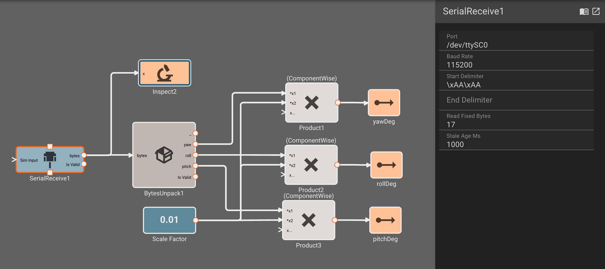
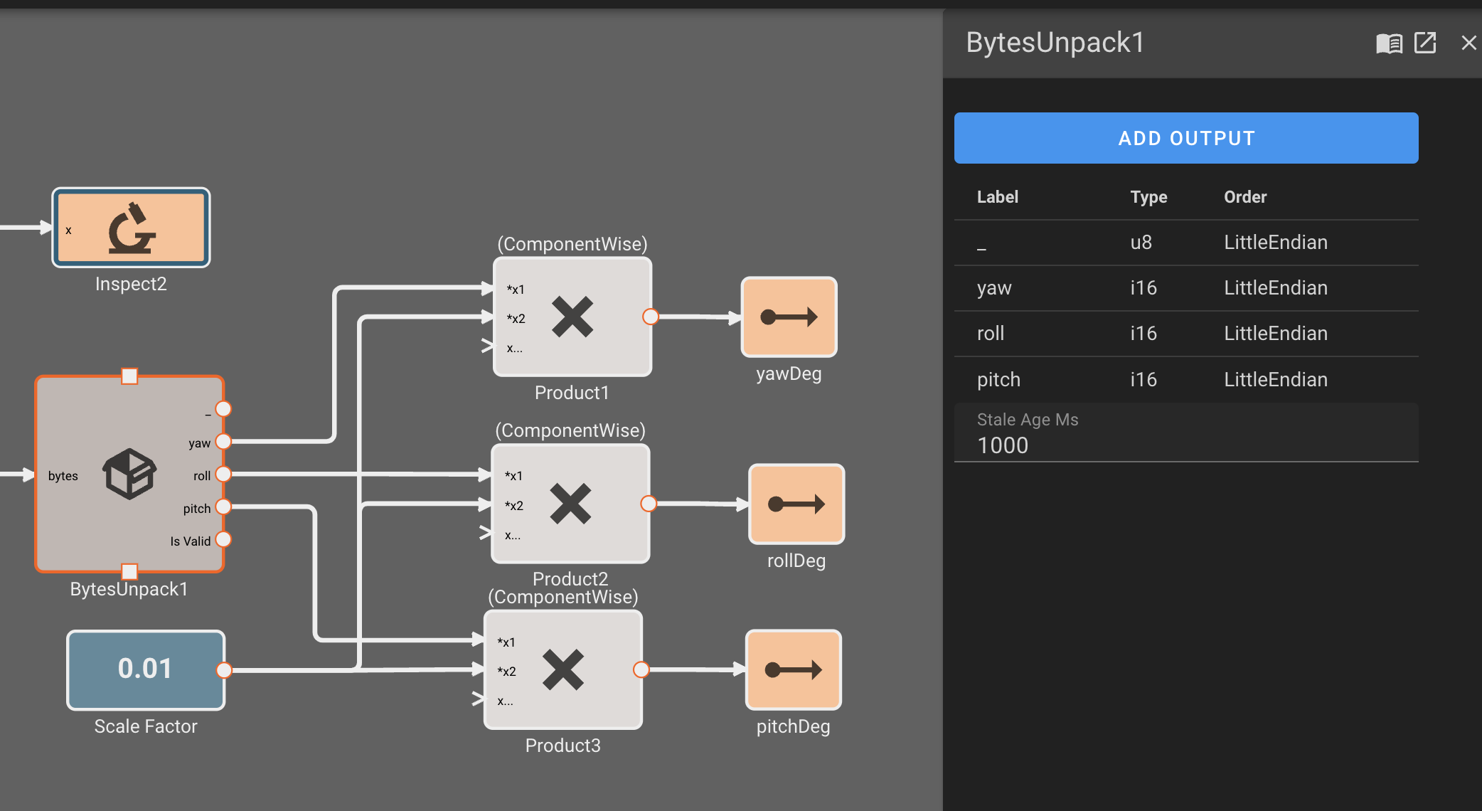
In our IMU ByteUnpack, we ignore the first u8 in the message, and then specify the signals we care about. Finally, we scale these integers by 0.01 to emit angles in floating point degrees:
This BNO085 IMU Component is also available in the public market for free use. Now that we've got stick inputs and IMU angles, it's time to write our controller!
Controlling Roll and Pitch Angles, and Yaw Rate
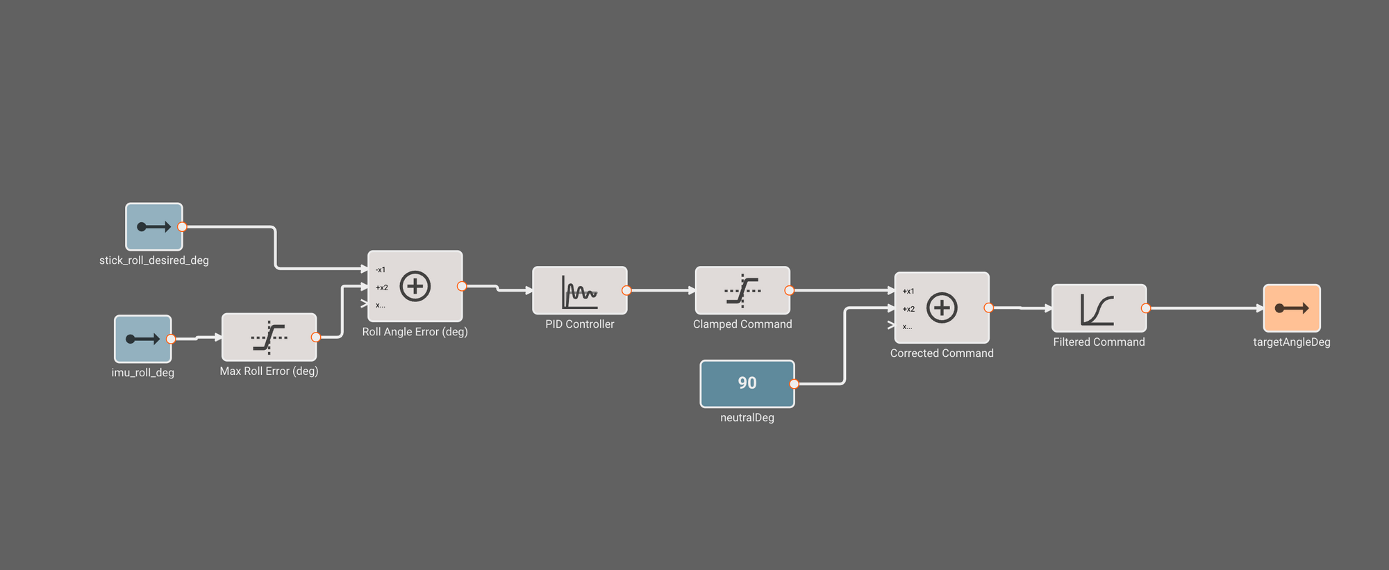
Our attitude controller is pretty straightforward - we read in the angle reported by the IMU, and subtract it from the stick input angle to form an error signal. Prior to subtraction, we clamp the IMU angle to about +/-20 deg, effectively limiting the amount of error we'll attempt to correct.
This error signal is propagated into a PID block, which we've tuned to give a nice stiff response without excessive overshoot. Just to be sure, we clamp the output command to the maximum possible deflection of our servos (45 degrees), which we then offset from the "neutral" stick position of 90 degrees. Finally, we apply some light filtering (IIR filter with time constant = 0.01s) on the final command to smooth noisy data. We pass this output to the servo driver block to issue commands over I2C.
The pitch and yaw axes are basically identical, except that yaw rate is being computed using a derivative block on the yaw angle signal, and treated as a disturbance to the yaw stick command.
Commanding Actuator Servos
To command the servos, we use a Servo Driver HAT from Waveshare that enables us to control up to 16 servos over I2C. Looking at the Wiki and demo code for the driver HAT, we find setup commands for this board that we can put in our "Initialize" state.
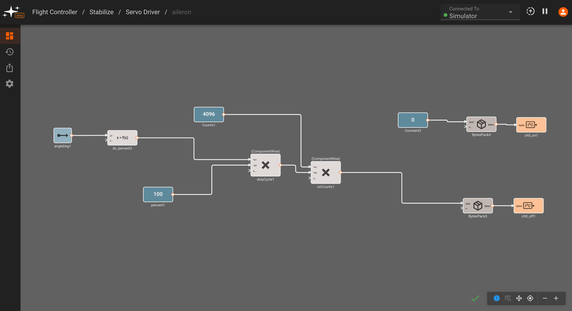
From our roll, pitch and yaw rate controller blocks covered in the previous section, we send individual target servo angles to servos attached to the plane's ailerons, elevator, and rudder. Within each servo driver component, we convert angles to PWM duty cycle, and then scale them to a value between 0-4096 to send to the right angle setting registered (again referencing the demo code for register values).
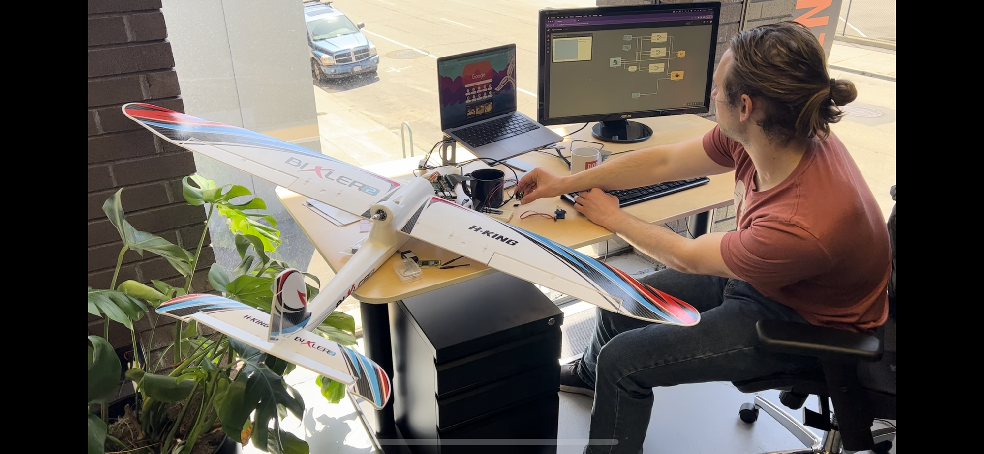
Deploy, Test, Iterate
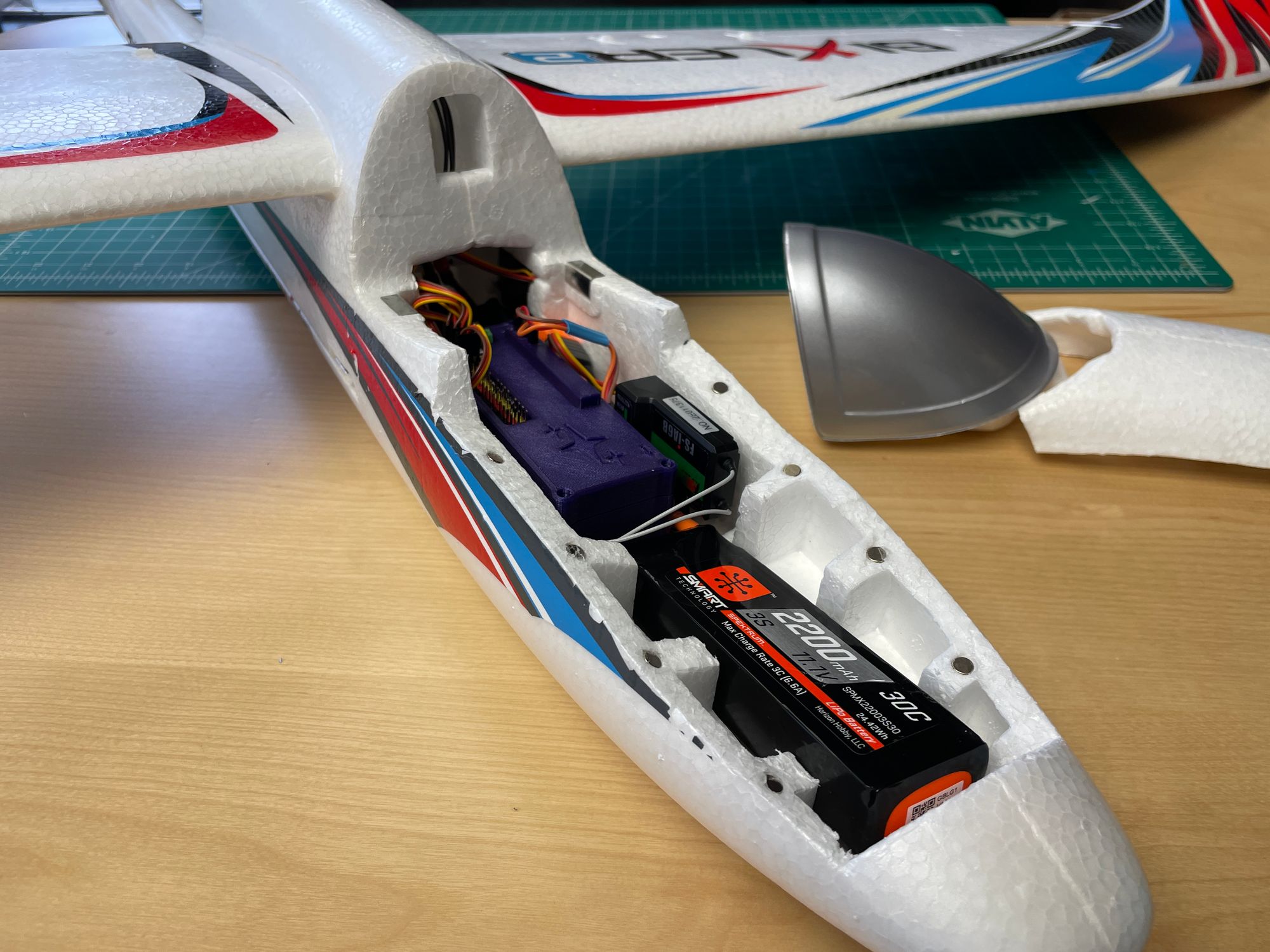
The fixed wing aircraft we're using is the popular Bixler 2. It's small enough to wrangle with one person, but large enough to resist light wind disturbances and fly easily. We carve out some foam in the nose to house our electronics (Raspberry Pi Zero, Serial Communication Hat and Servo Hat), which we've packaged into a custom 3d printed "black box" - except it's purple, and not indestructible.
3D printed case for flight controller electronics
We also wrap the plane in some nice heat tape for looks and to protect the foam.

Since the RaspberryPi Zero has a Wifi connection, we can wireless deploy software from Pictorus in the browser to the aircraft on our lab bench. Making sure to disconnect the propeller (safety third!), we then power the system and can experiment to verify our software is behaving as expected.
As we roll the aircraft one direction, the ailerons deflect (differentially) in the correct direction to induce a rolling moment to counter. If we move the roll stick input to match our tilt angle, the ailerons return to zero. Similarly, we test the elevator with pitch to confirm orientation.
Checking roll, pitch, and yaw values
Lastly, we gently shake the aircraft in a yawing motion, to see the yaw-rate damping in action. We make a few tweaks to flip directions since we got that one backwards, and tune the rate controller a bit, and then we're feeling good about our controller! One last test - that we can toggle the controller on and off using channel 5, and now it's time to go flying!
Tuning the yaw rate controller
Deploying To "Production"
One issue that Beta testers might encounter this year is that high frequency apps occasionally lock up briefly during telemetry transmission. Usually this isn't a problem for most devices and use cases, but when flying an aircraft, we can't risk even momentary loss of control of the vehicle. Eventually we'll make it easier to automatically deploy an app in "production mode", where telemetry is disabled and performance is optimized, but for now we need to do this manually.
We can achieve this by creating a SystemD service on our flight computer, and pointing it to the local Pictorus app. Then, we can temporarily stop the pictorus service, which closes our connection to the telemetry and app manager. This way, our flight controller app will run without any potential interference from Pictorus. Do this once you're ready to fly, because you'll need to re-start the pictorus service to get back to editing the app!
We've dedicated an entire blog post to this topic, if you'd like to read more.
Flight Testing!
We took the aircraft out to the Berkeley Marina, an RC park nearby that allows flying. We launched a few quadcopters into the sky to act as chase cameras, and then launched our aircraft by hand.
Initial flight, using our pre-heat wrapped prototype aircraft.
We started with autopilot flipped off, and let our pilot get comfortable flying the aircraft around the park. Our pilot was experienced enough to handle manual flying without much difficulty, so then came the moment of truth: Flipping the autopilot switch on, the aircraft jerked briefly as it moved into angle control, but then... flew beautifully!
After a few laps around the park, it was clear our yaw-rate controller was too aggressive, both fighting the pilot and making turns difficult, but also over-correcting and leading to an under-damped fishtail behavior. We disabled autopilot, landed the aircraft, and re-enabled Pictorus.
Controller tuning in the field
The wonderful thing here was it took us just a few minutes to tweak the controller from Pictorus over a laptop (tethered to a phone), update the aircraft software, and quickly re-deploy. We reduced yaw-rate dampening, and limited the total control authority of the autopilot, to give the pilot more control. If we were feeling extra brave, we could have left Pictorus in the loop and updated software mid-air, but given we were in a public space, erring on the side of safety seemed wise.
Within a few takeoffs, we had a pretty fantastic autopilot in the loop, and even the non-pilots were able to take a turn flying!
Footage from day 2, flying the final aircraft frame and tuned stabilization from day 1.
Conclusions
The fly day really showed off how powerful this software development paradigm can be. We didn't need to take the plane apart, or run any wires to it to update software. We didn't need a special laptop with special update software to iterate, we just got online and Pictorus handled it for us. Incremental compilation means small tweaks to the code only take a few seconds to recompile and redeploy.
Engineers often spend too much time pre-optimizing their software, when simply turning it on and trying it out will show you what you need to do next. A lot of this comes from force of habit, especially when toolchains are cumbersome and patching software or pulling down telemetry takes hours.
The easier we can make the iteration process, the more inclined we are to try things live - fail early, fail often, learn from your mistakes and improve your solution. The IDE can't get in the way, it has to be an ally in this effort.
If you'd like to try out Pictorus yourself, our Open Beta is free to the public. You can sign up at https://www.pictor.us.
Thanks for reading!