Setting up a Serial Communication Interface with Pictorus
In this post we'll demonstrate how to read radio transmitter data sent to a Raspberry Pi 4's dedicated UART interface, in order to control a Yahboom G1 Tank.

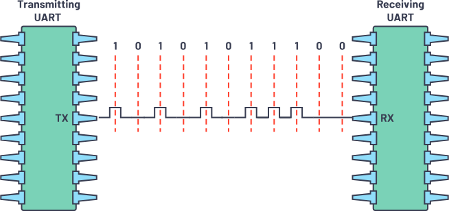
UART (universal asynchronous receiver-transmitter) is a widely used, hardware-integrated, device-to-device communication interface. It supports a range of serial data formats and transmission speeds, requiring only one or two wires to exchange information. In Pictorus, we can read and send data over UART using the Serial Receive and Serial Transmit blocks - we just need to specify the correct port and data format parameters.
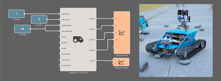
In this post we'll demonstrate how to read radio transmitter data sent to a Raspberry Pi 4's dedicated UART interface, in order to control a Yahboom G1 Tank. For more information about the Raspbery Pi-controlled tank and its onboard components, check out our blog post where we created an API for the Yahboom G1 in Pictorus.
Components
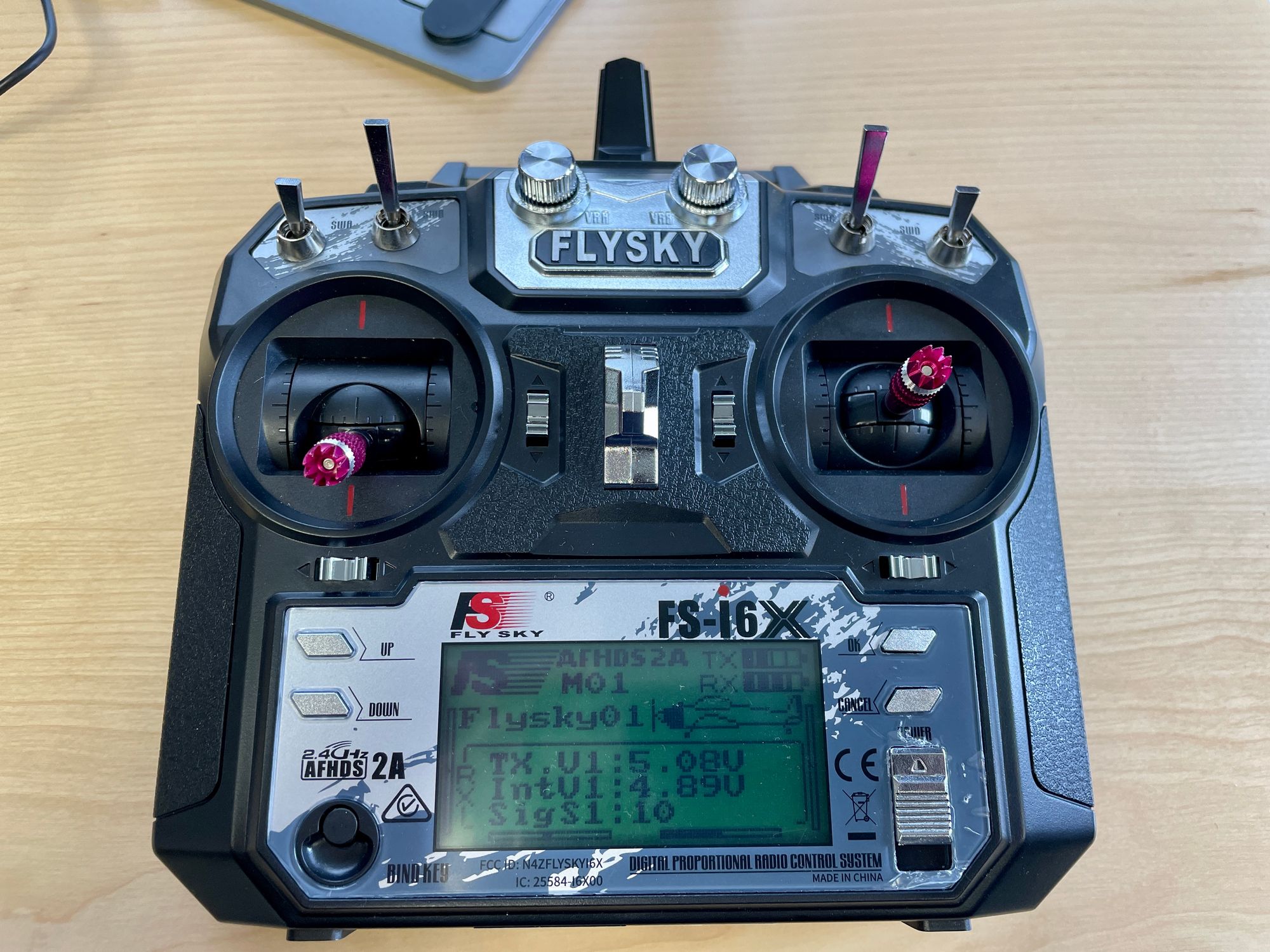
In addition to the Yahboom G1 tank, we'll be connecting a FlySky Fli4+ receiver to the tank's onboard Raspberry Pi and sending steering commands with the FlySky FS-i6x transmitter.
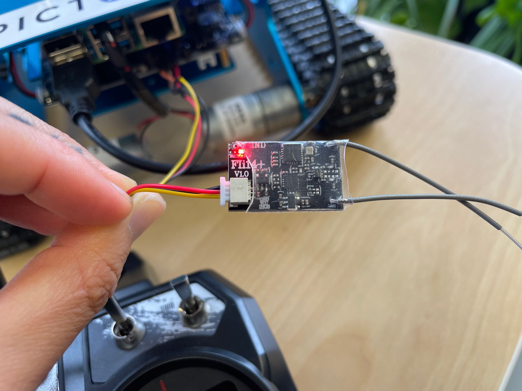
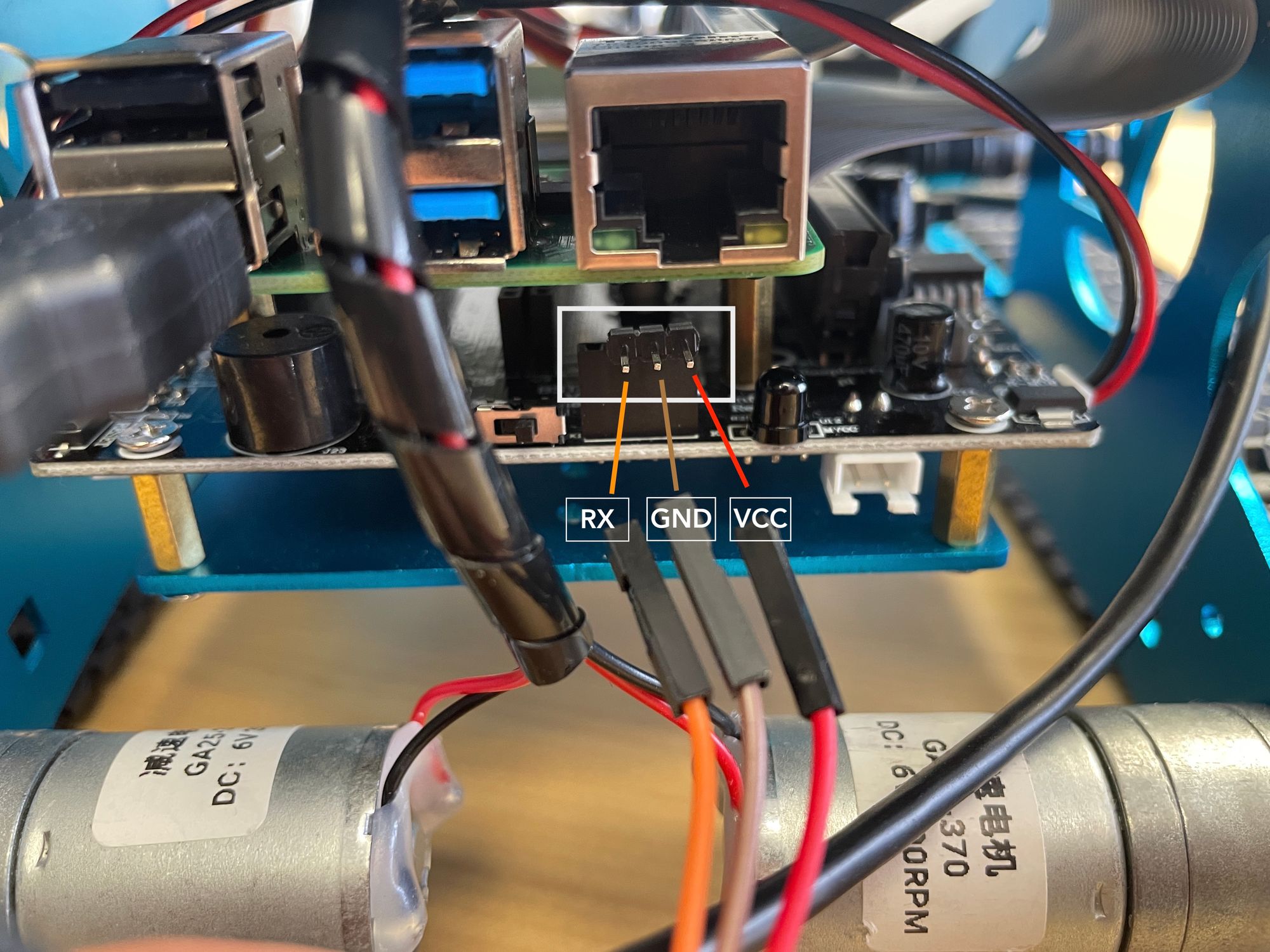
To receive data over UART on the Raspberry Pi, we connect the receiver to 5V power and ground, and wire up the data line of a receiver to the RX pin (GPIO15, BCM10) on the Pi.
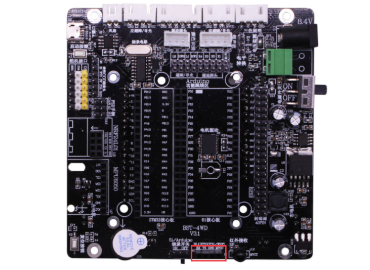
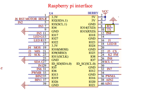
Since we're using Yahboom's Raspberry Pi expansion board, we need to find the correct ports that map to VCC, GND, and RX. Referencing the expansion board manual (downloadable here), we can find the appropriate connectors at the bottom edge of the board. Note that the Yahboom expansion board specifies these as Bluetooth connection pins, but we can see from the associated module schematic that these pins map to GPIO 14 and 15 (which we can configure to use as UART pins, rather than the default Bluetooth setting). For more information on the Raspberry Pi 4 UART and Bluetooth settings, check out this pinout guide and the official Raspberry Pi docs. The VCC and GND connections are also needed to power the receiver, so we'll be connecting to the rightmost three ports highlighted in red below.
Communication Protocol
In order to receive data, we'll first enable the UART interface on the tank's onboard Raspberry Pi. In the raspi-config tool, we navigate to Interface Options --> Serial Port. Following the onscreen prompts, we disable the login shell and enable the serial interface. Finally, we reboot the Pi for these changes to take effect. For more detailed instructions for setting this up - check out the "Configure UART on Raspberry Pi" section of this guide.
The transmitter-receiver pair in this blog post utilize FlySky's iBus communication protocol. This communication method is commonly used to control multiple servos and motors on RC planes, boats, cars, etc. utilizing a single digital line. For our purposes, we want to know what kind of data to expect from the transmitter and how to parse it.
Referencing the specifications for the FS- i6X radio transmitter, we find that we should expect a default of 6 channels of data. We also referenced a few blogs (such as this one) and libraries (such as this one) to find the baud rate (115200), start bits (0x20,0x40), stop bits(0xDC, 0x05), and data format (16bit little endian for each of 6 channels).
Now that we have data format and transmission speed information for this transmitter<>receiver pair, we can start parsing values from the controller. Note that our receiver should be connected to the primary UART on the Pi4, at /dev/ttyS0.
Receiving a byte stream from the RC transmitter after configuring the SerialReceive settings
Unpacking 6-channel data from serial data stream
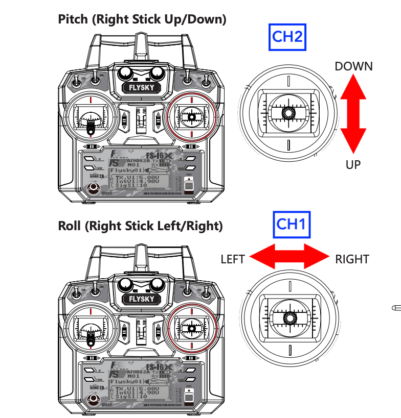
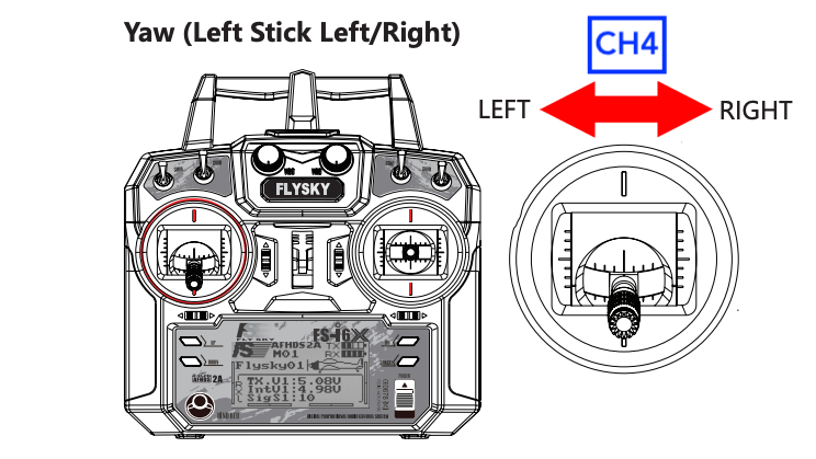
We can figure out which channel corresponds to which controller stick by plotting the outputs from all channels and seeing which channel changes value as we adjust the stick position. Using this method, we find that the left-right motion on the right controller stick corresponds to channel1, and the top-bottom motion on the right controller stick corresponds to channel2. These two axes of control will be enough to steer our robot forward/backward and left/right. As a bonus, we can use the left stick left-right control to control one of the auxiliary servos mounted on the Yahboom tank, such as the front rangefinder servo.
Plotting 6-channel data, reflecting motion in channel sticks
Using transmitted data to create an RC-driven tank
Now that we're receiving values from our radio transmitter and reading them in an app, we can scale and use them to control the motors on our tank.
We'll be interfacing with the Pictorus Yahboom tank API available in the component marketplace. As mentioned in the previous section, we'll use CH1 for left-right steering and CH2 for forward-backward motion in our tank. We will also move the front servo (holding the rangefinder) left-right with CH4.
By observing the plots in the previous section we can see that for each channel, the controller outputs a value in the range of 1500+/- 500. The first thing we need to do is scale each of these outputs to be in a +/-100 range, allowing us to map the percentage stick motion (from its neutral position) to a desired motor speed. We create components that handle these calculations for each channel.
Breaking out channels 1,2,4 to use for the tank controller and scaling to (-100,+100)
In order to steer the robot using the Yahboom tank component, we need two motor speed values (left and right, from 0 to 100), as well as two direction values (left and right, 0 or 1). To calculate speed, we sum the values from CH1 (left-right) and CH2 (up-down) after another round of scaling and appropriate sign adjustment for each direction. Note that we adjusted these scale factors and verified signs by deploying the app and testing it on the robot. For the direction values, we send '1's - corresponding to forward - if the control stick is above the neutral position, and '0's if the stick is below neutral.
For the servo motor, we take the scaled values from CH4 and use a Bias block followed by a Gain block to ensure that we're only driving the servo within an acceptable 0 to 180 degree range.
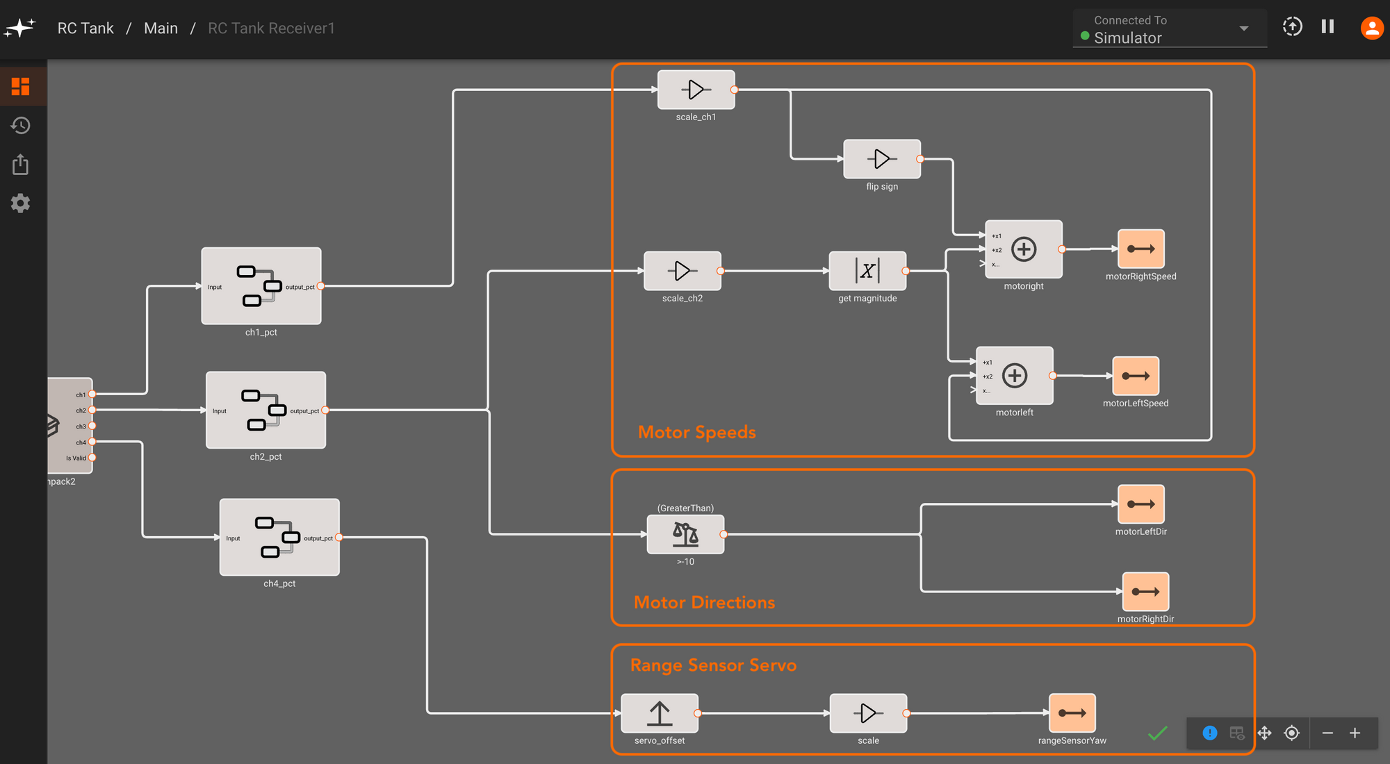
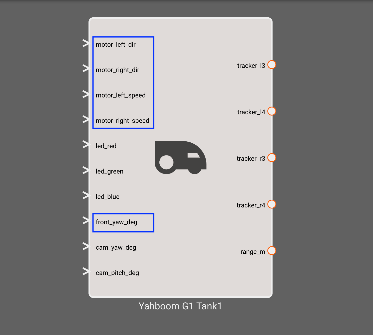
Now that we have correctly scaled outputs, we package this set of blocks into an RC tank receiver component. We can then connect the outputs to corresponding inputs on the Yahboom G1 Tank component, deploy the app and start steering the robot!
Connecting the RC receiver component to the Yahboom Tank API
Deploying the app and driving forward with the transmitter