Estimating range with an ultrasonic sensor using Pictorus
Ultrasonic rangefinders are everywhere in the robotics world. These devices emit acoustic pings outside our audible range to estimate short distances (within a few meters) from a hardware platform. In this post we'll demonstrate how to quickly connect to and get a range estimator up and running, with live telemetry, using Pictorus, which is currently a free software development platform in Open Beta. The component we build here will be available on the Pictorus public marketplace, so anyone can easily incorporate it into their own project.
Hardware Setup
We're using the HC SR04 from Adafruit, which is super common and cheaply available. This approach generally translates well to similar devices as well.
The HC-SR04 transmits a ping from one transducer, and measures the time of flight before the second transducer hears the reflected ping. As shown in the animation, care must be taken to ignore self-noise from the device when estimating distances.
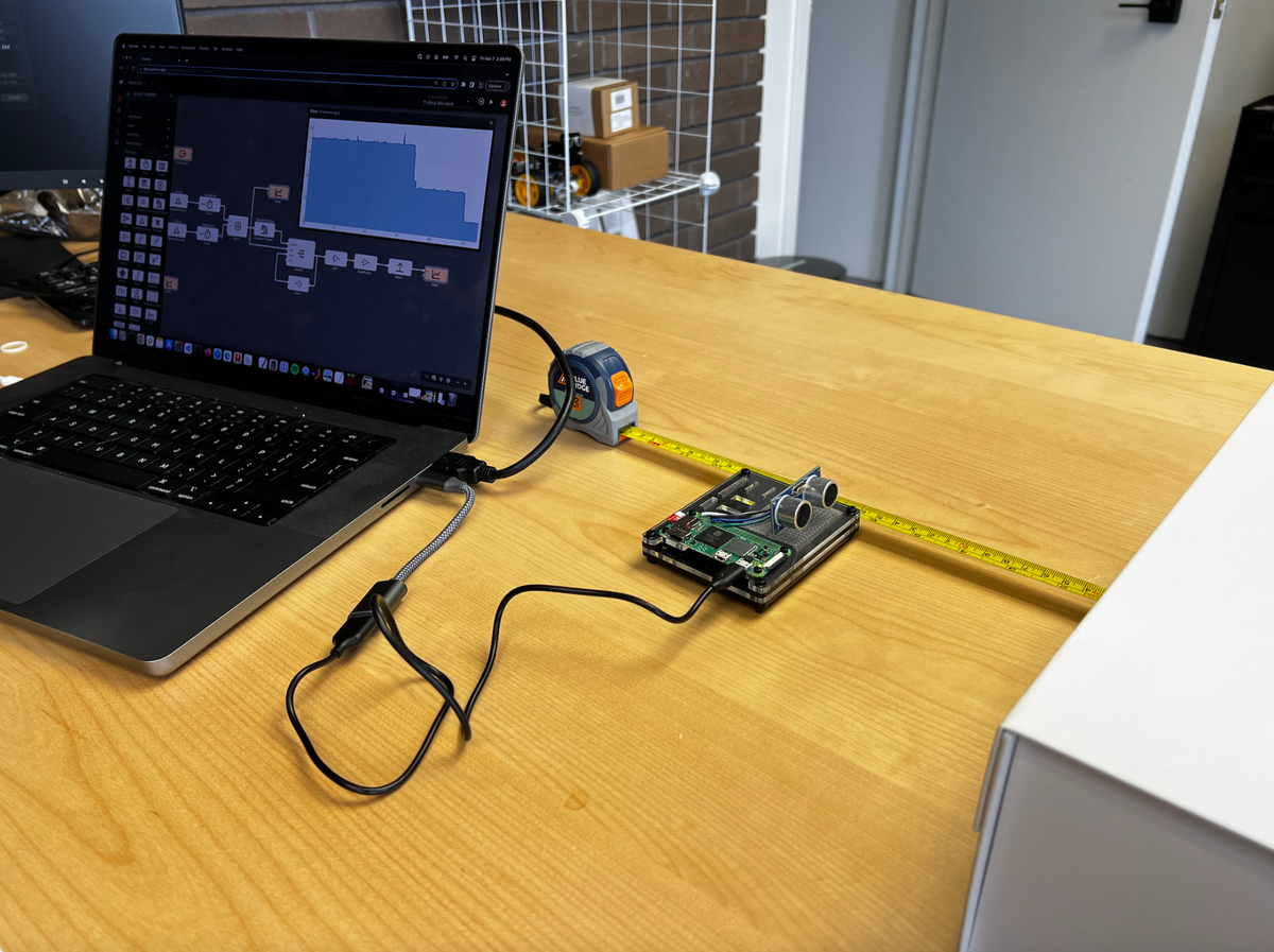
Some quick background: The device has four pins - VCC, GND, Trig and Echo, which can be easily wired up as shown below (we used a RaspberryPi). There's a wire for power (VCC), ground (GND), transmit (Trig) and receive (Echo). There's a lot of great explainer articles which deep-dive into the internal workings of the device if you're curious. We'll focus instead on how to design an application for interacting with the ultrasonic sensor.

Some Background on Software Dev using Pictorus
Some folks have used visual coding tools in the past to program hardware, like Scratch or Blockly. If you come from the engineering world, you might be most familiar with Simulink by Mathworks.
Pictorus is most functionally similar to Simulink, and the block diagram workflow will be familiar. The biggest difference is that Pictorus comes ready to compile, deploy, and manage app execution for you right out of the box, for free. There is very little to configure, you just install it on your dev board, load up your web browser, and get coding.
Unlike Scratch and Blockly, which primarily deal with scripted languages, Pictorus not only generates high performing Rust code for you, but we also compile the apps, in real time, and sync them to your device with the push of a button. Compiling Rust code allows us to build much more powerful apps that can run on a wider variety of hardware than is otherwise possible with other visual programming tools.
Designing the Range Finder App
We'll start by creating a new app titled "Range Finder."

Make sure your dev device is synced to Pictorus, so we can automatically push software to it from the browser. Once connected, let's try communicating with the sensor! We'll start by sending a simple ping pattern to the transmit pin, to verify we hear echos coming back.
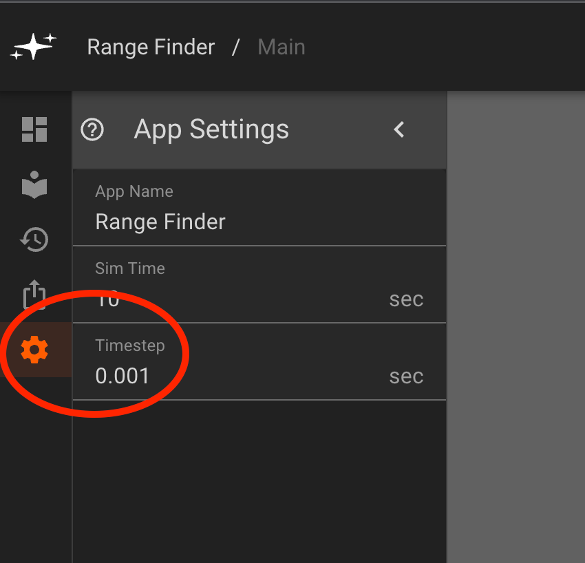
As always, we consult the device datasheet, which explains that we need to send a trigger pulse for at least 10ms, and advises a 60ms measurement cycle to listen for the echo pulse. So we need this app to run with an update interval of at least 10ms. For good measure, we'll start with an update rate of 1ms. We can configure this using the App Settings menu from the left panel, indicated with a gear icon. We set the timestep to 0.001s.
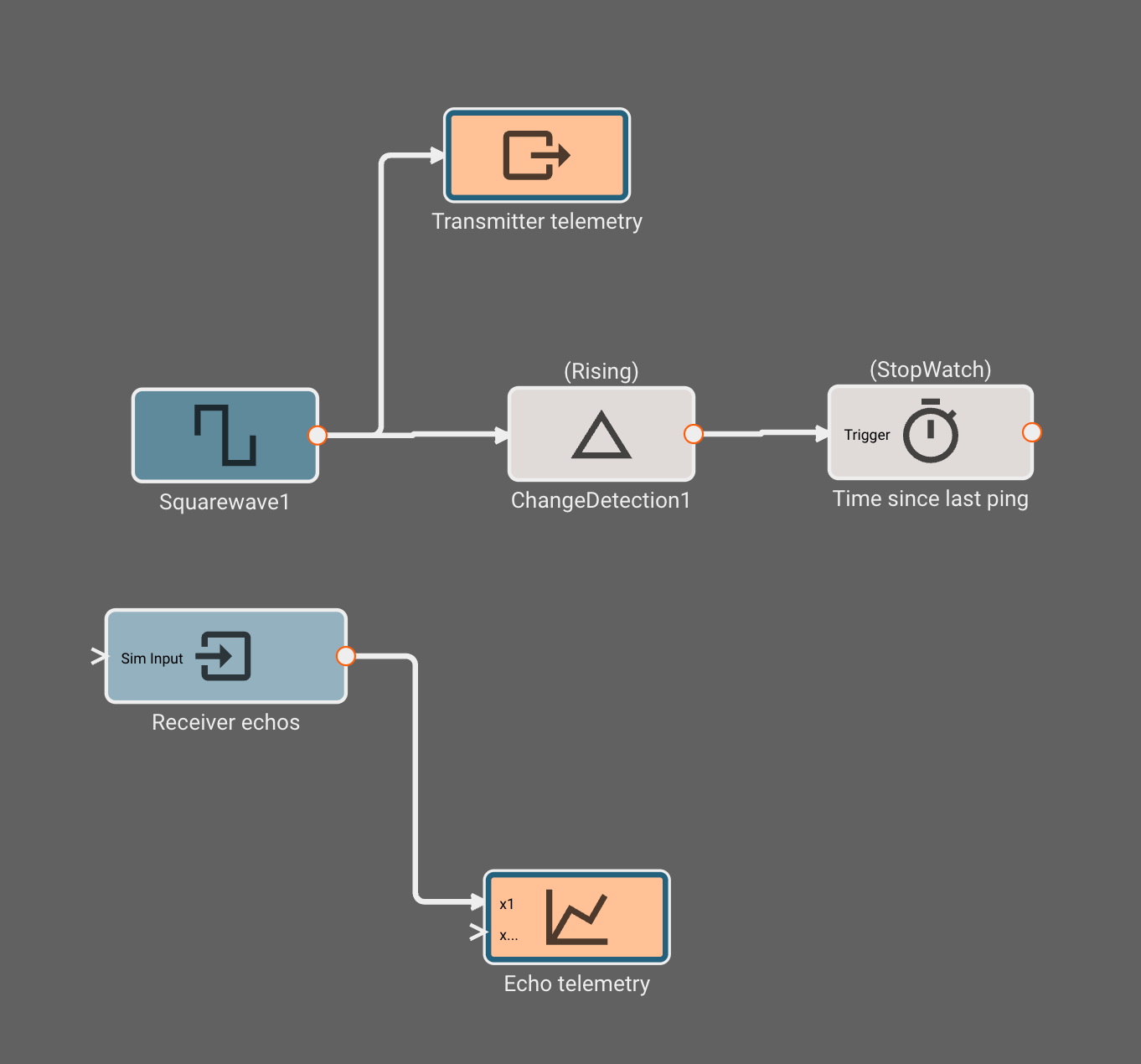
Now that our app is configured to run at a sufficient update interval, we can start diagraming the app's logical flow. We can generate the ping signal using a Squarewave block from the generators tab. By default, it is set to generate one second high/low pulses. We double click the block to open its parameters, and update them to 10ms (the transmit time) on, 60ms (the measurement cycle) off. With this pattern, we should be able to confirm the device is transmitting and receiving ping data.
To actually send the ping signal to the transmitter, we add a GPIO Output block, and configure it to transmit on pin 4, matching our wiring diagram. Yours could be different, so double check the pins!
Next, we add a GPIO Input block to receive telemetry from the receiver pin, which for us is pin 27. Finally, by adding a Plot block and connecting the new GPIO Input to it, we should have an app that transmits and receives data.
Let's give it a shot! In the upper right, we click to deploy the app to our device. In about 5-10s, we should get confirmation that the app is deployed successfully. Then we click run to start the app.
With any luck, we should start seeing telemetry stream back in the next 10-15 seconds. When the Plot block shows a heavy blue outline, that means it has data to show, and we can double click to open the live telemetry stream.
And there we go! Telemetry starts steaming to our timeseries plot, continuously updating as new data arrives from our device. We can pause or resume the app any time by clicking run/stop. From this timeseries, it's clear that the receiver is hearing the echos from transmission. Note: Recent app updates have disabled automatic plotting of GPIO outputs. To view the squarewave that's sent to the transmitter pin, simply connect a plot block to the Squarewave block.
Designing the range estimation algorithm
Now that we've confirmed our sensor is working, it's time to design a range estimator. All we have currently are pings, we need to convert those into distance estimates.
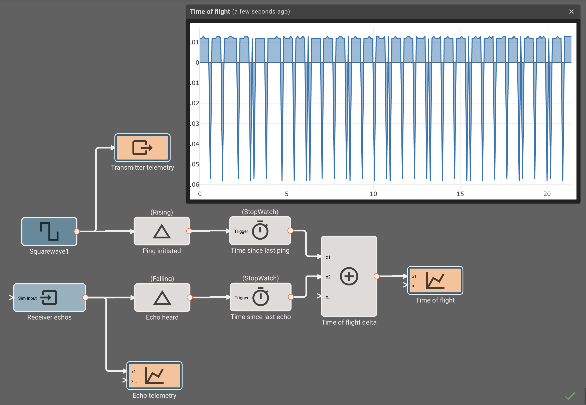
To do this, let's record the time between when we transmit a ping, and when the reflection is heard. We add a Timer block to our app, and configure it to stopwatch mode. This will track how much time has passed since its input was last true. Between the Squarewave generator and the Timer, we insert a ChangeDetection block, configured to emit true when the input signal from the Squarewave is rising.
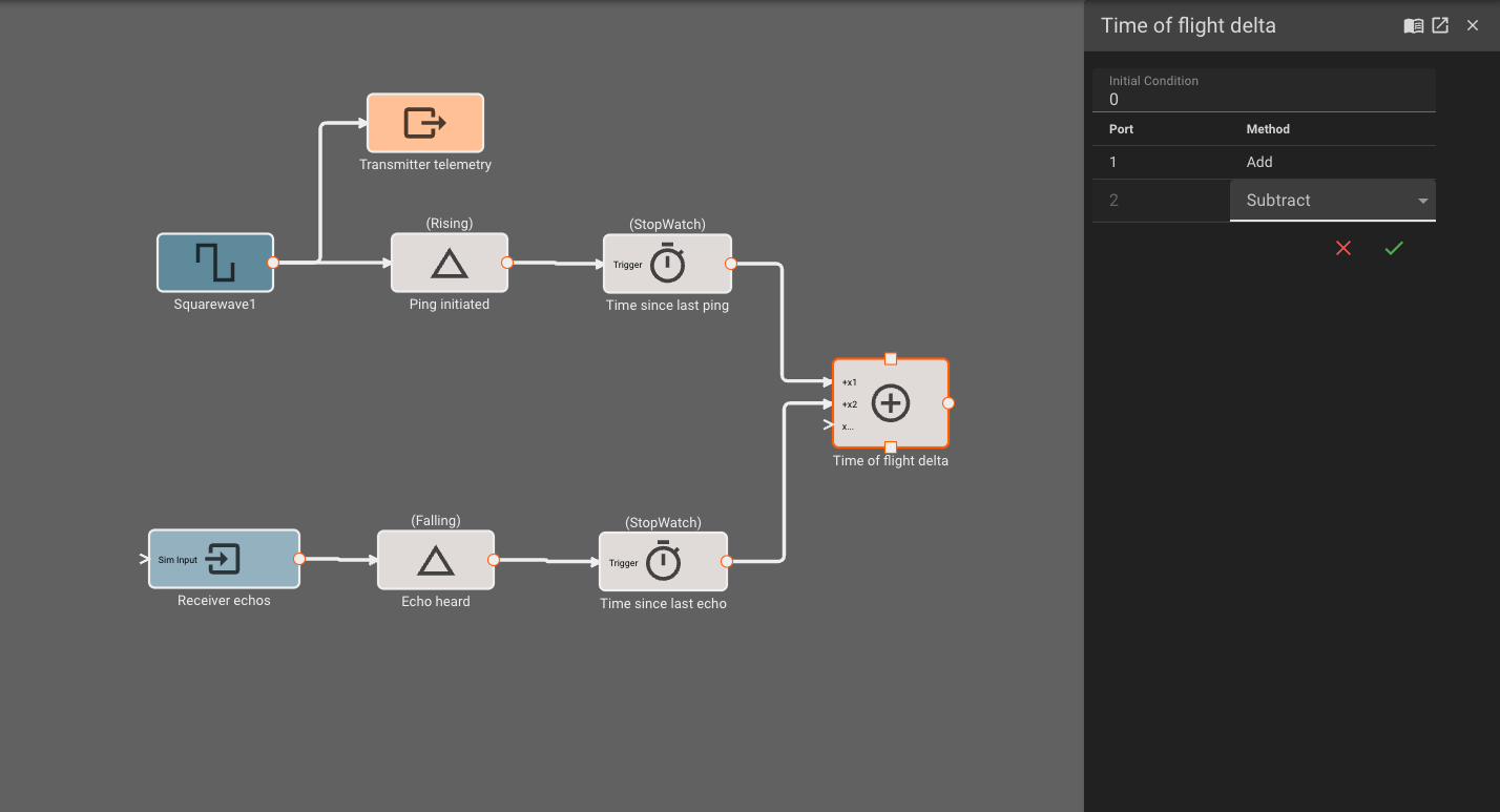
This sequence of blocks will now track the time since the beginning of the last transmit pulse. One simple way to estimate the echo time is to simply subtract this timer's value from a similar timer tracking falling echo signals (receiver is high when nothing heard, goes low when echo heard). We can replicate the timer sequence for the receiver, and connect them both to a Sum block, setting the second port to "Subtract" from the first.
Once we attach this summation signal to a plot and re-deploy, we see the echo time deltas in our timeseries. Occasionally the value is negative (indicating a missed ping, or self-noise) so we'll have to filter those measurements out.
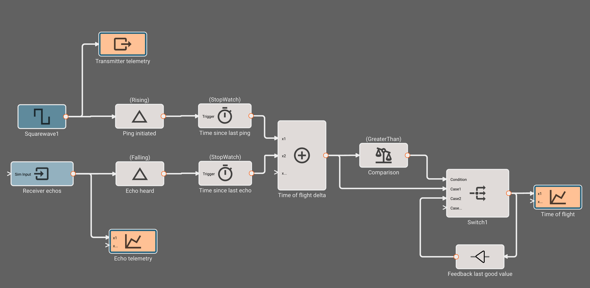
We drop a CompareToValue block, and indicate we want to know if the signal is greater than zero. Then, we connect this comparison to the condition inport of a Switch block, and the time delta to second inport, indicating we'd like to pass it through if the comparison is true. Lastly, we feed back the output of the switch to its third port, indicating we'd like to hold the last value if the condition is false.
Coverting "Time of Flight" to Distance
The last step is to convert the time estimate into a distance estimate. Since the time of flight represents both the time to an obstacle as well as the time back, we multiply by half the speed of sound to get our distance. We're using inches per second here, since that's easier to confirm with a tape measure than the typically expected metric meters.
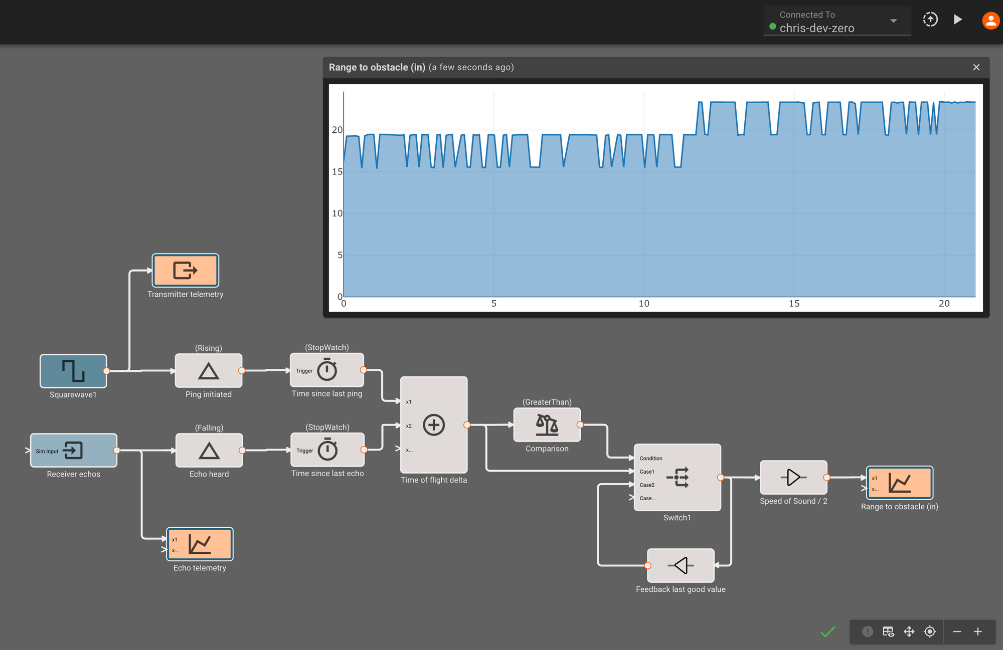
Re-deploying this app, we finally see distance estimates! Although they look roughly correct, it appears like the estimates aren't very precise, jumping around in about ~7in increments as we move something in front of the sensor. This is because although 1ms update rate is technically fast enough to interact with the sensor, it only gives us a resolution of 0.001s * (13503.9/2.0) = 6.75in, because the speed of sound (13503.9 in/sec) is fast relative to our update rate.
Faster App == Better Estimates
Luckily, the fix is easy - faster update rate! The spec sheet advertises a minimum range of 4cm, which would correspond to an update rate of about 0.25ms. It's good practice to run software at least twice as fast as the phenomenon you're estimating, so by decreasing the app timestep to 0.0001s, we should be running fast enough to get smooth distances between 4cm and several meters. This is now a 10,000 hertz application, so it's a good thing we're compiling to high-performant Rust executables!
There's a few more things we can do here to improve estimates further without much effort. First, we can add a simple digital filter to our estimator to help reject noise. We can also compensate for other sources of error introduced by communication delay and sensor particularities by taking some ground truth measurements with a tape measure, comparing them to the raw estimates in browser, and computing corrective bias and scale factor terms.
At this point, we've got a pretty decent, calibrated distance estimator! If you'd like to use this estimator in your own application, you can find the component on our public marketplace. You might want to re-calibrate those last two blocks, as each sensor will manifest different errors and biases.
When to use acoustic range finders (and when not)
Acoustic range finders like the SR04 are a lot of fun to tinker with, because they're cheap and easy to work with. For most simple robotic applications, where the maximum distances are short, velocities aren't too high, and acoustic interference isn't a concern, these devices work wonderfully.
It's also good to know when you should consider time-of-flight sensors that use light instead of sound. Devices using the speed of light, instead of the speed of sound, can offer a significant range and accuracy advantage over acoustic sensors like the SR04. These devices aren't sensitive to high-frequency noise (like around quadcopter propellers), and don't suffer doppler-effect errors when the device is moving quickly (aircraft, automobiles, etc), nor are they greatly affected by temperature or humidity.
But Lidar has its own drawbacks. If your setting has a lot of electromagnetic interference, the sensors can suffer just as acoustic sensors do in the presence of high-frequency noise. They're often more expensive, harder to work with, and in some cases heavy. In short, they can be overkill if the situation doesn't call for it.
A final note about using this estimator in your apps
It might be impractical to force an app which wants to use this range estimate to run at 10kHz. In the future, we'll make it easier to run different parts of your app at different rates, but for now it's wise to just build separate executables for applications which need to run at significantly different rates, and have those apps communicate to each other over some protocol.
We have one blog post here on how to deploy apps permanently to your devices. And another post here detailing how to get apps to communicate with each other over UDP.