Building a DIY Thermostat with Pictorus

In this post, we will run through the design of a simple home automation device - a thermostat - using Pictorus. Along the way we’ll showcase a few extensible functionalities within our app including talking to sensors using the I2C protocol, building up reusable components and sensor APIs, and implementing input/output control in Pictorus.
Thermostat Functionality Overview
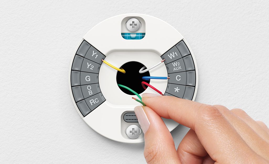
If you’re not already familiar, a basic thermostat functions as a switch that controls whether a few elements are on or off (in our case, a furnace and a fan), based on a user’s desired temperature setpoint. If you remove the thermostat on a wall, there are usually 2-8 color-coded wires meant to distribute power to different parts of your HVAC system. For our fan-and-heater control system, we will connect to G (furnace) and W (fan) wires. We will also grab wall power from the R wire to power our thermostat. Note that we are interfacing with a low voltage HVAC system (24V) in this project, which is commonly found in American homes and used to control a range of heating systems such as furnaces, heat pumps, baseboard heaters, and central AC.
HVAC System Caution
A quick, hopefully obvious word of caution - HVAC systems vary widely, and some are easier and safer to control directly than others. Always make sure you understand any system you tinker with and take appropriate electrical and fire safety measures.
In order to switch the fan and heater on or off, we will utilize a 24V relay driven by a Raspberry Pi Zero (RPi). We chose this single-board computer since it packs most of the Raspberry Pi functionalities in a much lighter weight form factor, and is also commonly used in DIY Internet of Things (IoT) projects.
The thermostat will allow users to adjust temperature or automatically turn a fan on or off to circulate air throughout a space. In Pictorus, we can set up control logic to understand the temperature setpoint or fan on/off state and send an appropriate switching signal to each of the relay channels. Using the I2C protocol, the app will read temperatures from our BME280 (temperature, barometric pressure, humidity) sensor and also display the current temperature or temperature setpoint (if it’s being adjusted) on a screen.
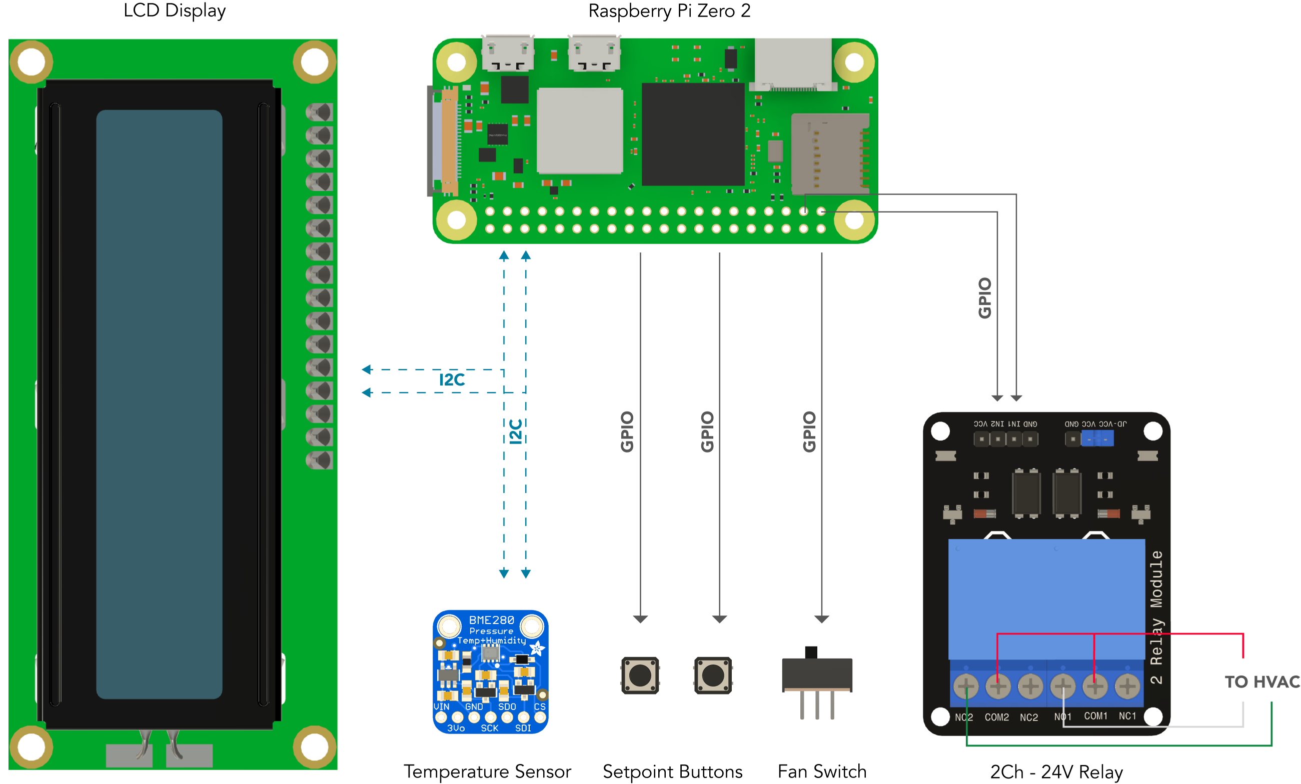
Here is our vision for the overall system:
Temperature Sensor Setup
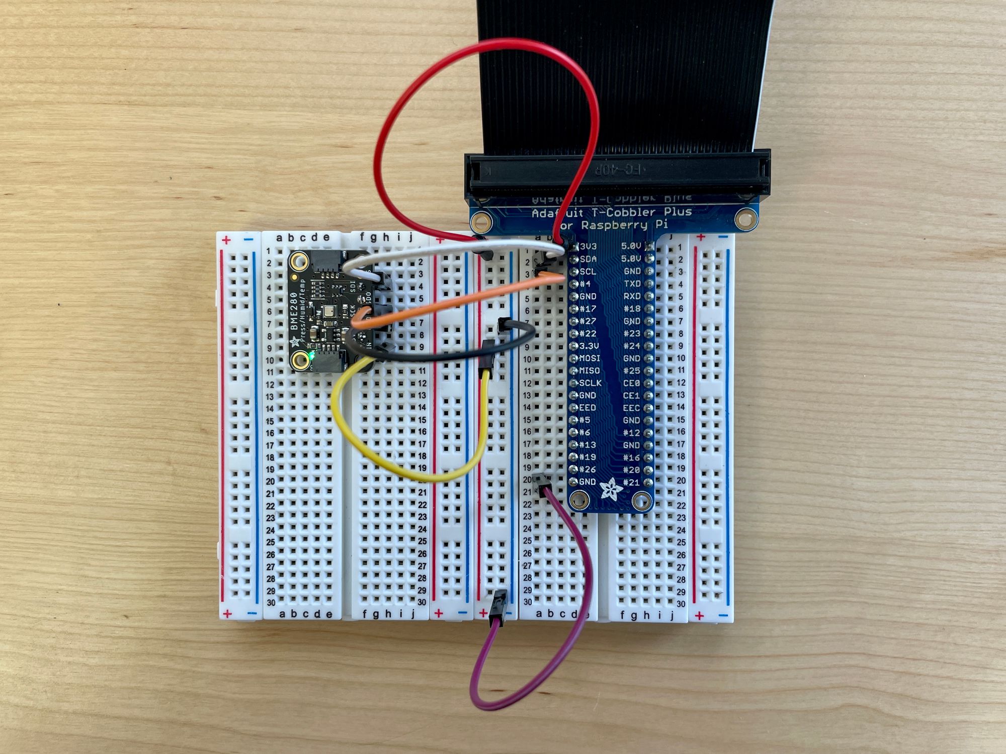
We purchased a BME280 sensor breakout board from Adafruit, which makes connecting and communicating to the sensor over I2C fairly straightforward and also well documented. In this section we’ll go over how to communicate with this sensor in Pictorus.
I2C Overview
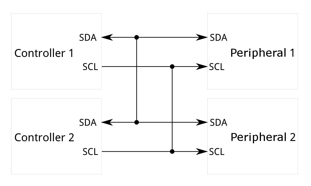
As a brief refresher, I2C is a short-distance communication protocol that only requires two wires and allows us to send commands to a device or receive data from a device over the “data” wire (SDA) using a well-defined protocol and a unique address for each device. The other wire (SCL) functions as a clock to coordinate data to and from the device.
A nice feature of Pictorus is we don’t have to know a whole lot about I2C to interact with devices. As long as we can read the data sheet (or existing source code), we can configure an I2C block to either read from or command any I2C device connected to our board.
BME280 I2C Commands
Using either the Bosch datasheet or Adafruit’s BME280 python library as reference, we can send over a series of I2C read or write commands to the sensor in order to set its mode, read factory calibration coefficients, and receive a stream of data. We’ll go over the setup for temperature sensing in this blog post, but the BME280 component - publicly available in the Pictorus marketplace - contains functionality for reading temperature, pressure and humidity.
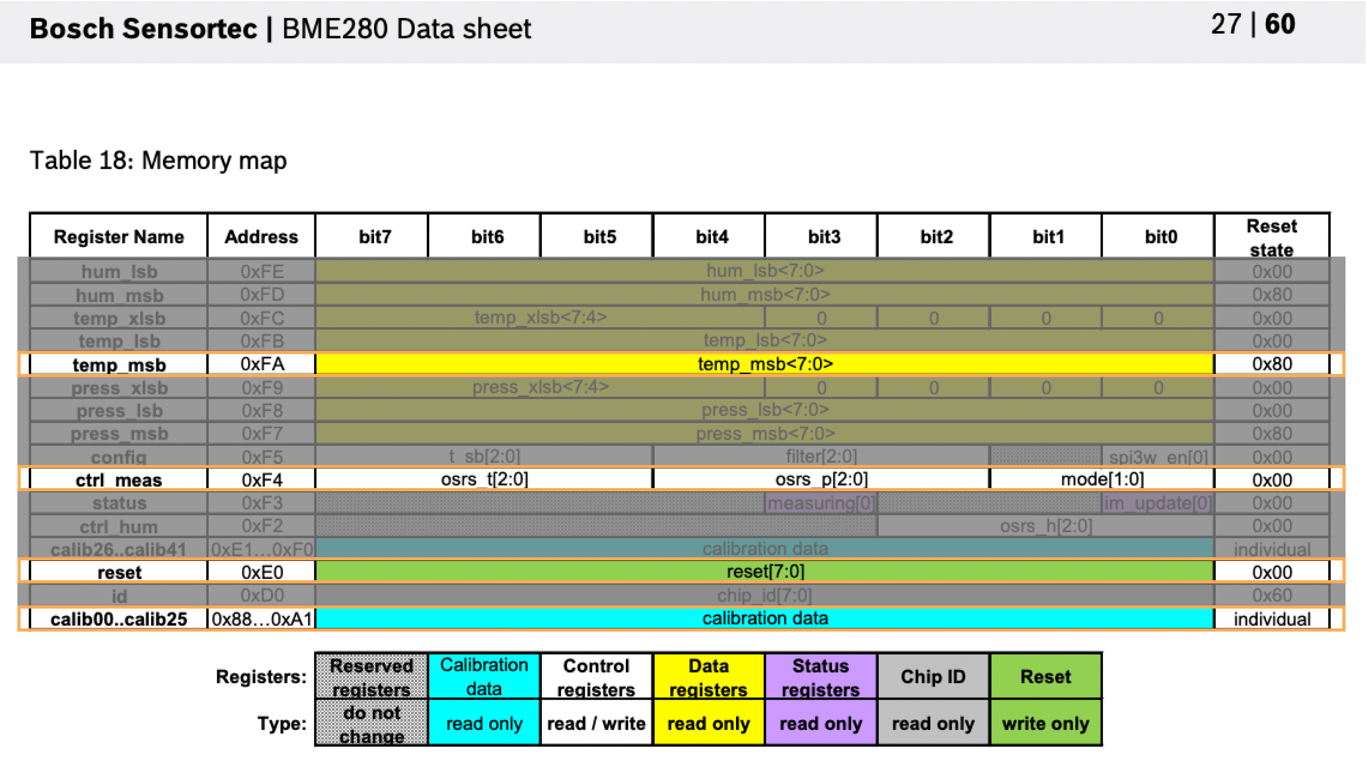
For temperature readings, the first step is a setup sequence that consists of sending a soft reset command to the sensor, setting the data read mode, and reading the sensor’s calibration coefficients. Relevant registers and constants can be found either in the “General Information” section of the referenced Python script or in Section 5 of the data sheet. We’ll be working with those highlighted in the data sheet below.
1. Sensor Setup
For the first few milliseconds as the app starts up, we will write the soft reset command 0xB4 (182) to the “reset” register 0xE0 (224). In Pictorus, we can do this with an I2C output block.
Once the soft reset command is packaged up into a component, we can set this to run within the first two milliseconds of the app running using an AppTime block.
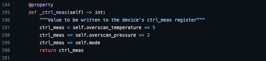
Then, in the 2ms after, we will write the data read settings to the “ctrl_meas” register, 0xF4 (244). To set temperature overscanning and start the sensor in normal mode, we write the value 0x37 (55).*
Note that the value 0x37 was calculated following the math in the BME280 library Python snippet shown below:
2. Reading Calibration Coefficients
In addition to writing the measurement configuration settings, we read the sensor’s calibration coefficients from register 0x88 (136). The first three coefficients, or first 6 bytes in the register, are utilized for temperature reading compensation.
We can add an AppTime block for this sequence (reset, data read configuration, getting coefficients) to occur in the first 4ms of the app running. Afterwards we will start reading data.
3. Reading Raw Sensor Data
In order to read sensor data, we use an I2cInput block for address 0xFA (250). The first 3 bytes will correspond to temperature data.
At this point, we can build and deploy our app to a Raspberry Pi Zero. The raw sensor data can be plotted to confirm that things are running as expected.
3. Calculating Calibrated Temperature
After some math with coefficients (and following the read_temperature function in the Adafruit Python library script) we can get a calibrated temperature output from the sensor.
We can handle calibration equations that require multivariable inputs using Equation blocks as needed.
We continue to build up the calibration sequence, finally sending the temperature in degrees Celsius to a component output.
4. Grouping Blocks into a Component
We then group the blocks into a single component named BME280. This component will contain custom variables - corresponding to the calibration coefficients. We set these as variables in order to be able to reference them as outputs or inputs for any blocks within the BME280 component.
The final steps in building out the component functionality are to feed in the right coefficients to the "read temperature block" and a "temperature (deg C)" component output.
Using a plot block, we can observe calibrated temperature changes as we warm the sensor up.
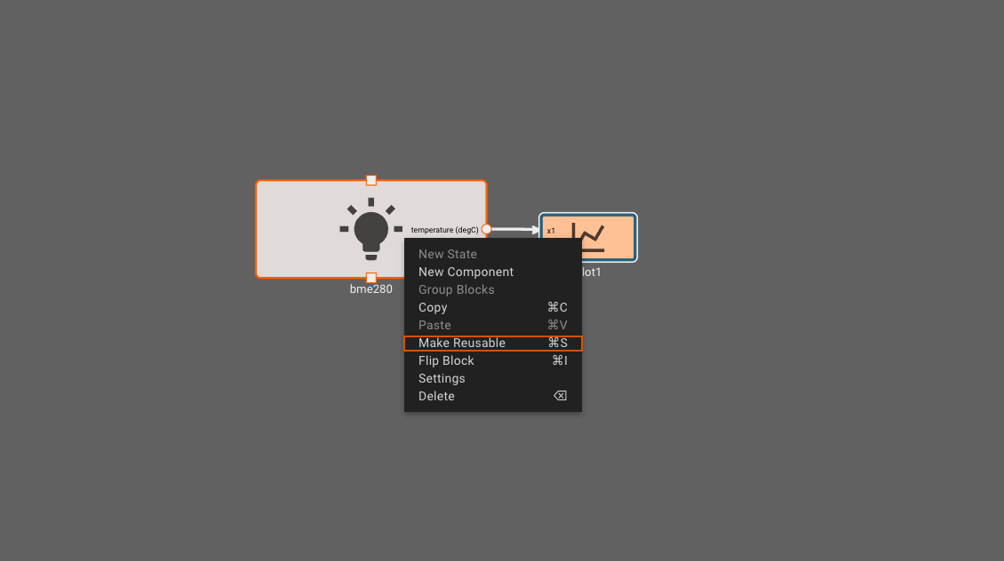
That wraps up the temperature sensing BME280 component build! In order to reuse the setup and math we just did, we can make the component reusable by right clicking on the component and selecting "Make Reusable."
Thermostat App Design
The DIY Thermostat app needs to fulfill four basic functions:
- Read the room temperature
- Determine a setpoint based on button presses
- Turn a fan and heater on or off by comparing the current temperature to the desired setpoint temperature
- Turn a fan on if a user switches the fan to the on position
- Display the setpoint as its being adjusted, otherwise display the current temperature
Here is a (rough) sketch of our wiring diagram, with a Pictorus app controlling communication between the Raspberry Pi and the peripherals:
1. Reading the room temperature
We’ve already done step 1 in the previous section, so we will move on to other components of the app.
2. Determining a setpoint
For step 2, we can build a simple up-down counter using a series of summing blocks and two gain blocks that allow for each button press to incrementally change a value. We also add an offset (of 68) to this value in order for the setpoint to start around an expected desired room temperature.
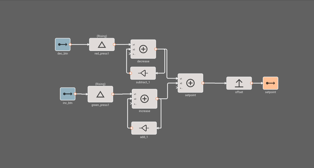
This can be packaged up in a “determine setpoint” component with GPIO inputs set to the correct pins on the Raspberry Pi.
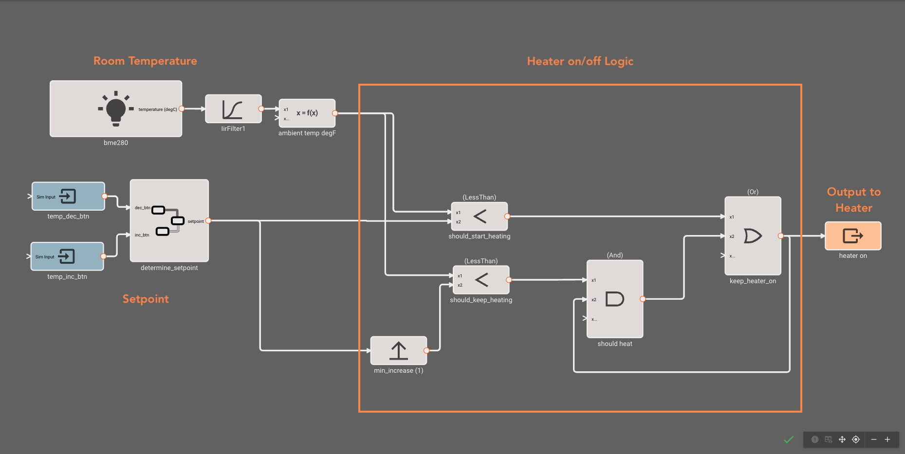
3. Heater and Fan On/Off Logic
In step 3, we compare the temperature sensor readings to the desired temperature setpoint in order to turn the heater and fan on or off. The heater and fan (let’s call this “heat” for short) are turned on together in order for hot air to circulate throughout the space. The series of blocks below compare the current temperature to the desired setpoint, turning the heat on if the setpoint is lower than the setpoint and only turning it off after we have increased the room temperature by 1 degree.
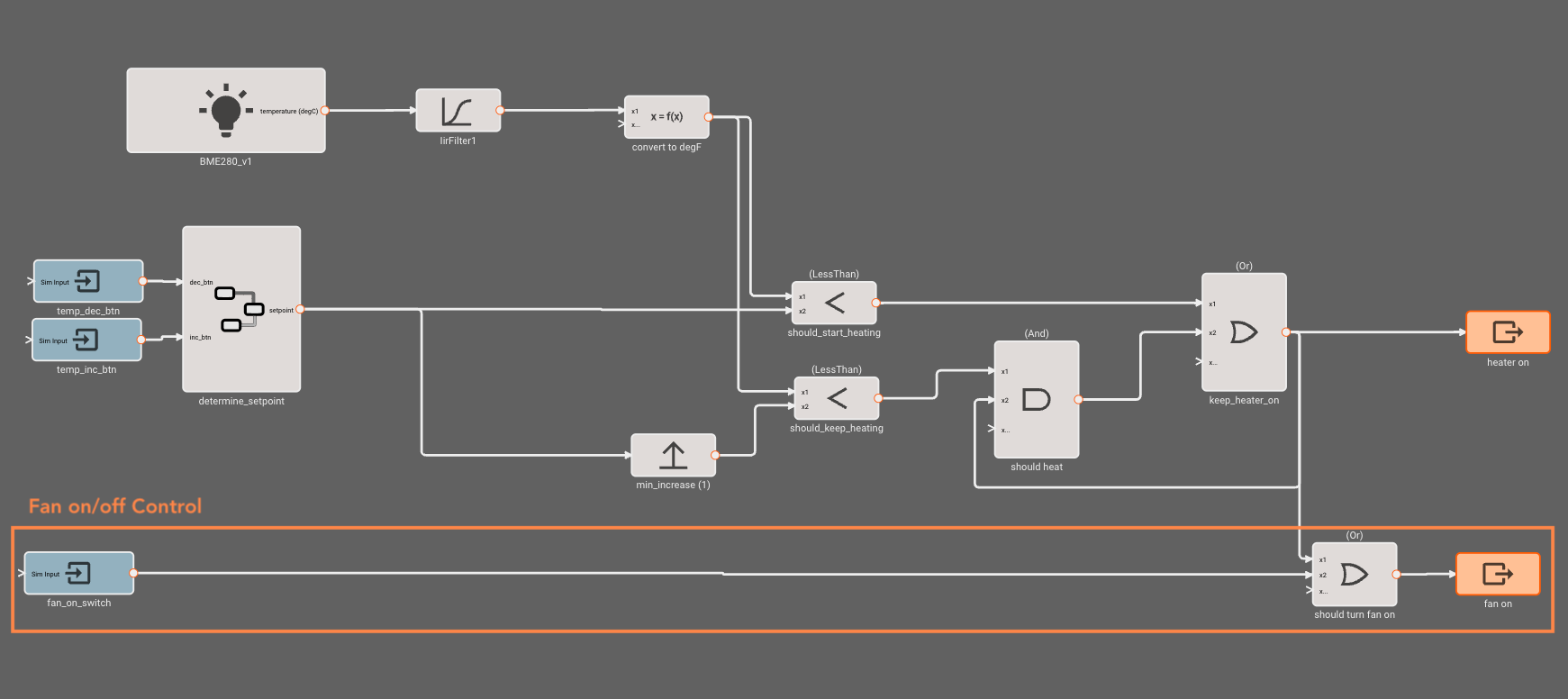
4. Fan On/Off Logic
The last control we need to add - in step 4 - is a couple of blocks that turn the fan on when the switch is set to the “on” position (or when the heater is on).
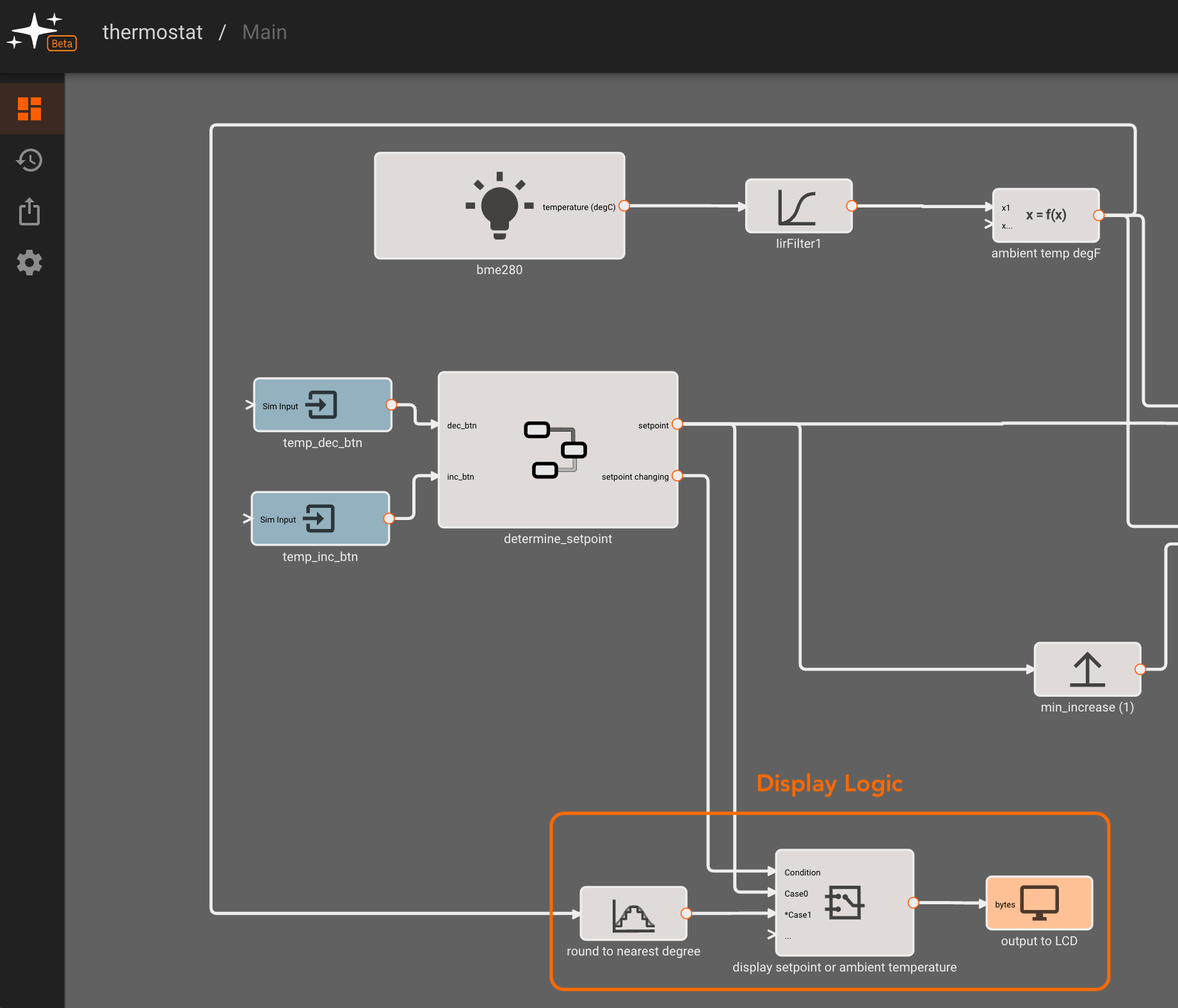
5. Setpoint Display
Finally, we want to display the current room temperature or the desired temperature setpoint as someone is adjusting it.
Sending data to a screen is fairly straightforward with the Display block. Currently, this block supports standard character LCDs (using an HD44780 controller) or OLEDs (using an SSD1306 controller) over I2C. All we need to do is enter the display’s address - 39 for our character LCD and feed in a numerical input. The display block also allows for an X Offset - in case we want to center the value on the screen or offset it depending on what part of the screen is visible in the physical setup.
To toggle between displaying the currently sensed temperature we use a Switch block. In the case that the setpoint is being changed (with a buffer of 2s after a button pressed is detected), then we will display the current setpoint. Otherwise, we display the sensed temperature.
In order to do this, we add a “setpoint changing” output to the “determine_setpoint” component which then feeds into a switch block, as shown below. In the third inlet, we feed the sensed temperature, converted to degrees Fahrenheit and rounded to the nearest degree.
Assembling the DIY Thermostat
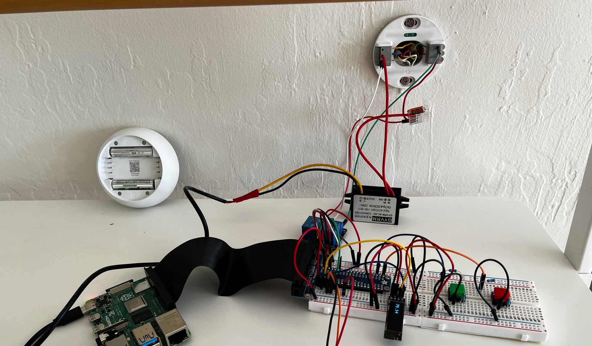
1. Functional Testing
Before starting the assembly of our system, we can first check that our thermostat works as expected by mocking it up on a breadboard with jumper wires. This is also a good time to check that our interface with the wall thermostat wiring is as expected, before designing an enclosure. For this first functional test, we used a Raspberry Pi4.
2. Enclosure Design and 3D Printing
Now that the app is complete and functioning with breadboarded components, we can 3D model and print a case to house the electronics and provide an interface to connect to the wall wires. We will use a Raspberry Pi Zero and a protoboard HAT to reduce the overall footprint of our circuit.
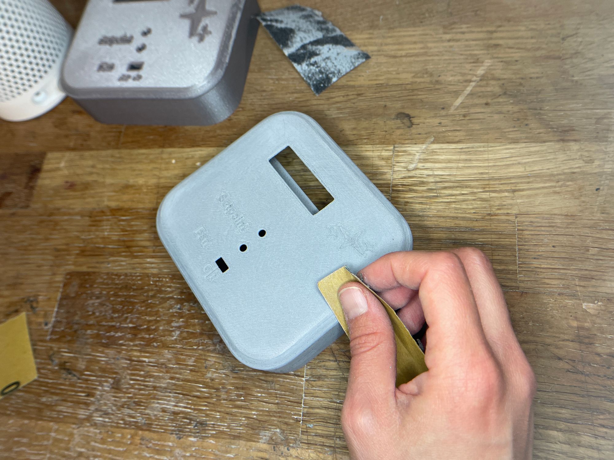
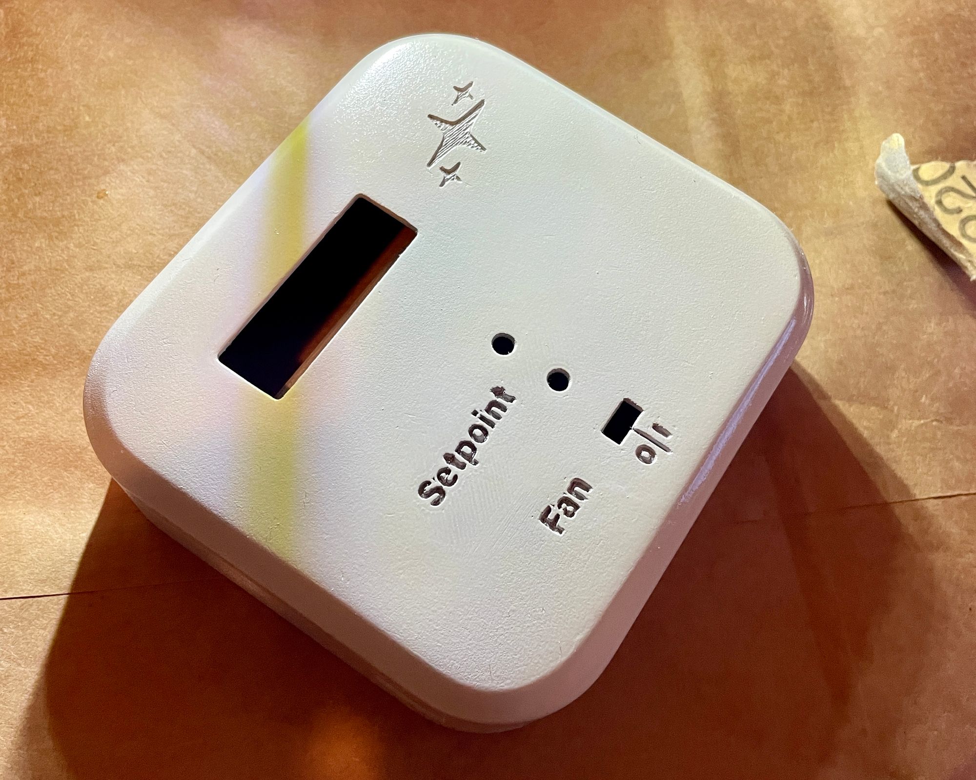
3. Enclosure Finishing
Once the enclosure parts are printed, we finish the front face with a few cycles of sanding-priming-painting.
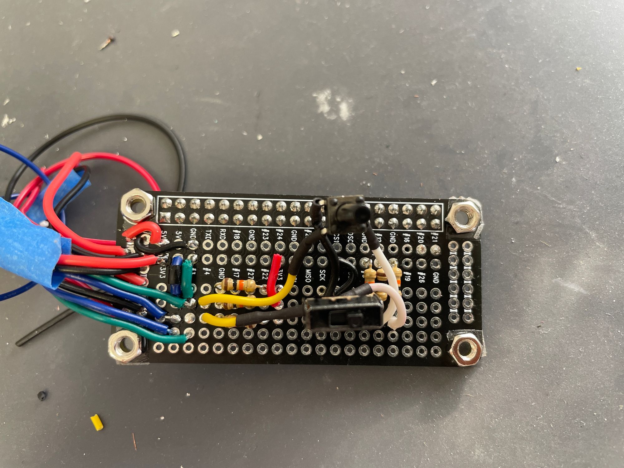
3. Soldering, Wiring, and Integration
After soldering everything onto a protoboard - we used this stackable one for the Pi Zero - we can secure all components within the enclosure using heat set inserts and screws.
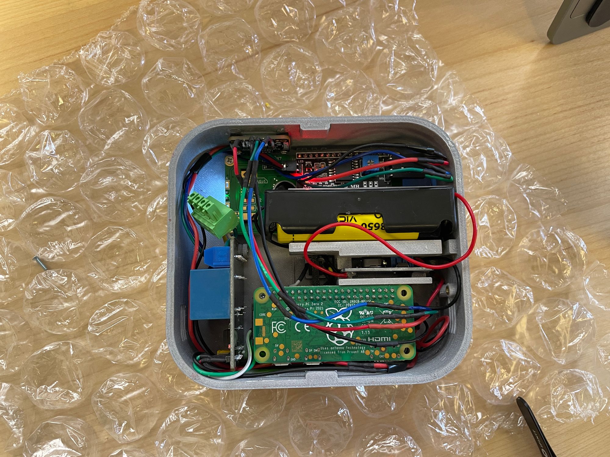
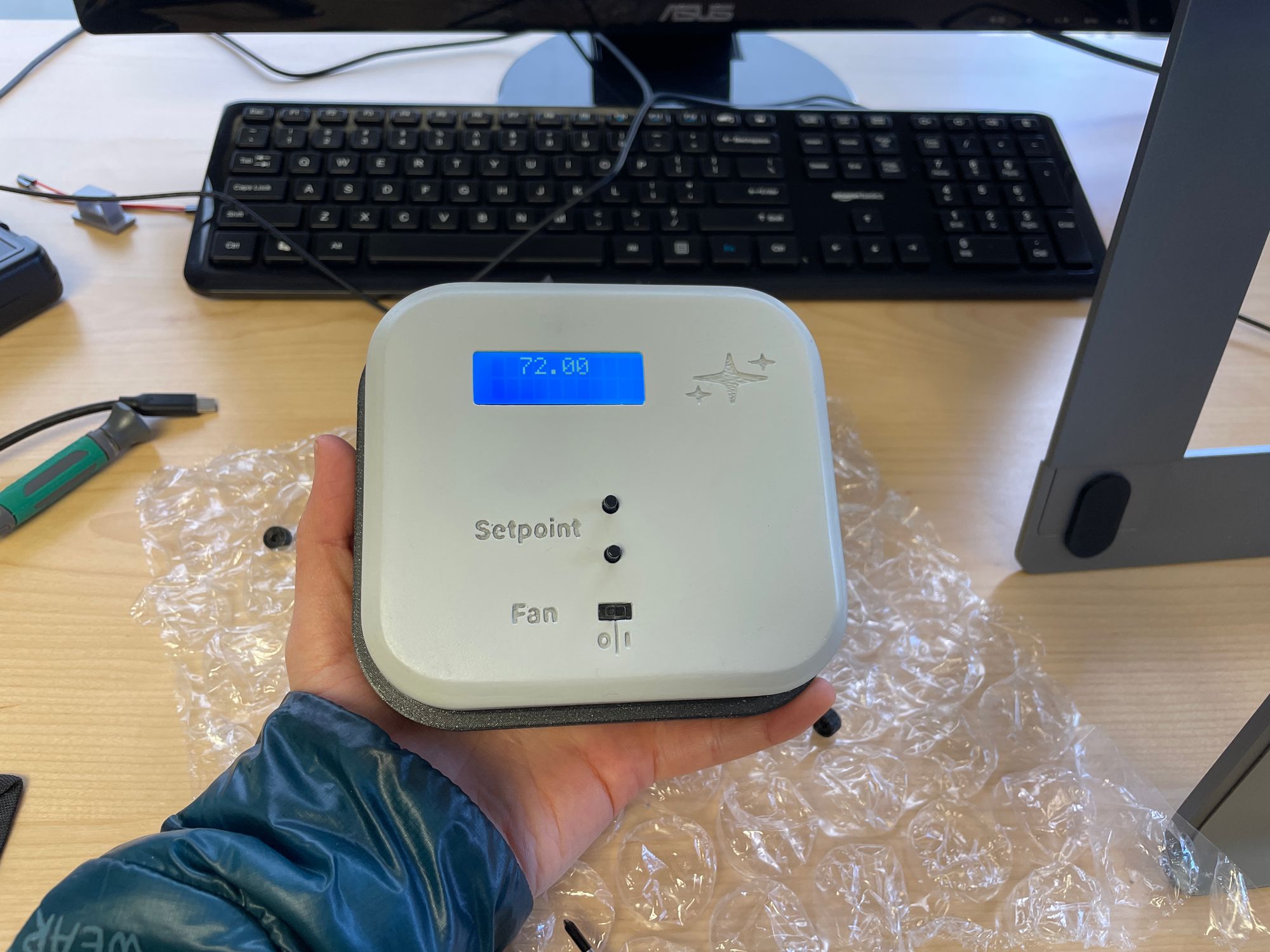
Here is the final assembly with the top fitting snugly into the back plate:
4. Final Test
Before installing the final version onto a wall, we test the app again, now running on a battery-powered Pi Zero and within an enclosure. To do this, we can open up the app in Pictorus and plot our inputs and outputs. We verify that outputs are switching on and off as expected and that the display shows the correct temperature information.
Once we have all of our components secured and functionality verified, we can install the thermostat - ensuring that we connect to the correct HVAC wires - and run our app remotely using Pictorus.
Once we have all of our components secured and functionality verified, we can mount the enclosure onto the wall connecting to the correct HVAC wires, and run our app remotely using Pictorus.
Final Notes
Extending our DIY Thermostat Functionality
The thermostat we designed in this project is fairly minimal in its functionality - operating in a single mode, essentially as a switch based on two inputs (temperature setpoint, fan on/off) and a sensed temperature. In a next project, we can envision adding a few more features, bringing our DIY thermostat closer to the functionality of smart or programmable thermostats. For instance, we can add the ability to schedule automated temperature changes based on time of day and day the week - aiming at a more efficient usage of our heating/cooling system. The user interface for this could be as simple as adding a couple more mode-setting buttons and an on-screen series of scheduling options to click through.
In Pictorus, we can set up scheduled thermostat operating modes as different states. For more information about working with multiple states within apps, check out our States documentation, or projects such as the Obstacle-Avoiding Robot or Plantbot. More than this, we could also record and publish data about our HVAC system usage - making analysis of our energy usage accessible via a web dashboard, for instance. To see an example of how to publish data over UDP in order to render it in a web dashboard, check out the last section of our Plantbot blog post.
Working with other sensors in Pictorus
In this project we set up communication with the BME280 pressure, humidity, temp sensor using I2C input and output blocks. The steps we took in the sensor setup section can be easily extended to other common I2C-powered sensors - such as GPS, accelerometer, or range finding modules. All that's needed is a reference to the read and write commands to enter in our block parameters.
We will continue to publish I2C-powered sensor components in our marketplace, as well as those using other protocols, such as UART. We are also excited to see users helping to build out and build upon our library of supported sensors!