Building an Obstacle-Avoiding Robot using Pictorus
In this post, we'll program an obstacle-avoiding robot to autonomously drive around a room. It will detect barriers by pivoting its HC SR04 ultrasonic sensor to scan nearby surroundings.
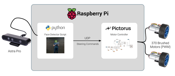
In earlier blog posts, we demonstrated how to use an ultrasonic sensor connected to a Raspberry Pi to estimate the distance to nearby objects. We also showed how to build up an API for controlling a robot with many sensors and actuators.
In this post, we'll go a step further - by programming an obstacle-avoiding robot to autonomously drive around a room. It will detect barriers by pivoting its HC SR04 ultrasonic sensor to scan nearby surroundings. Based on what the robot "sees", it will command power to two DC motors to steer forward, backwards, left or right.
The basic principle is similar to how early Roomba-like cleaning robots randomly navigated households. Those robots use more advanced lidar and computer vision sensors these days, but this is still a fun and illustrative robotics project. In particular, we'll dive into the State Machine workflow in Pictorus, which is a powerful way to describe and control the logical flow of your apps.
Required Components Refresher
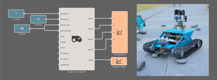
Our prior blog posts introduced all the hardware we'll need for this robot: An off the shelf Yahboom G1 Tank, which includes a RaspberryPi single board computer. We installed Pictorus on that computer over ethernet, and are ready to deploy compiled software directly from our browser. The Yahboom G1 has a variety of sensors and actuators to interface with. For this project we'll focus on:
- The HC SR04 ultrasonic sensor, which we previously built and deployed a custom RangeFinder app for estimating distances to nearby obstacles. This will alert us when we're too close to an obstacle.
- The two brushed DC motors, which control the robot's movement forward and backward at adjustable speed for turning.
- The forward mounted servo motor, upon which the HC SR04 sits. We can command angles to sweep a 60 degree cone in front of the robot to look for obstacles.
- The three LED lights, which allow us to command a visual indication of what the robot is doing.
Understanding the State Machine Approach
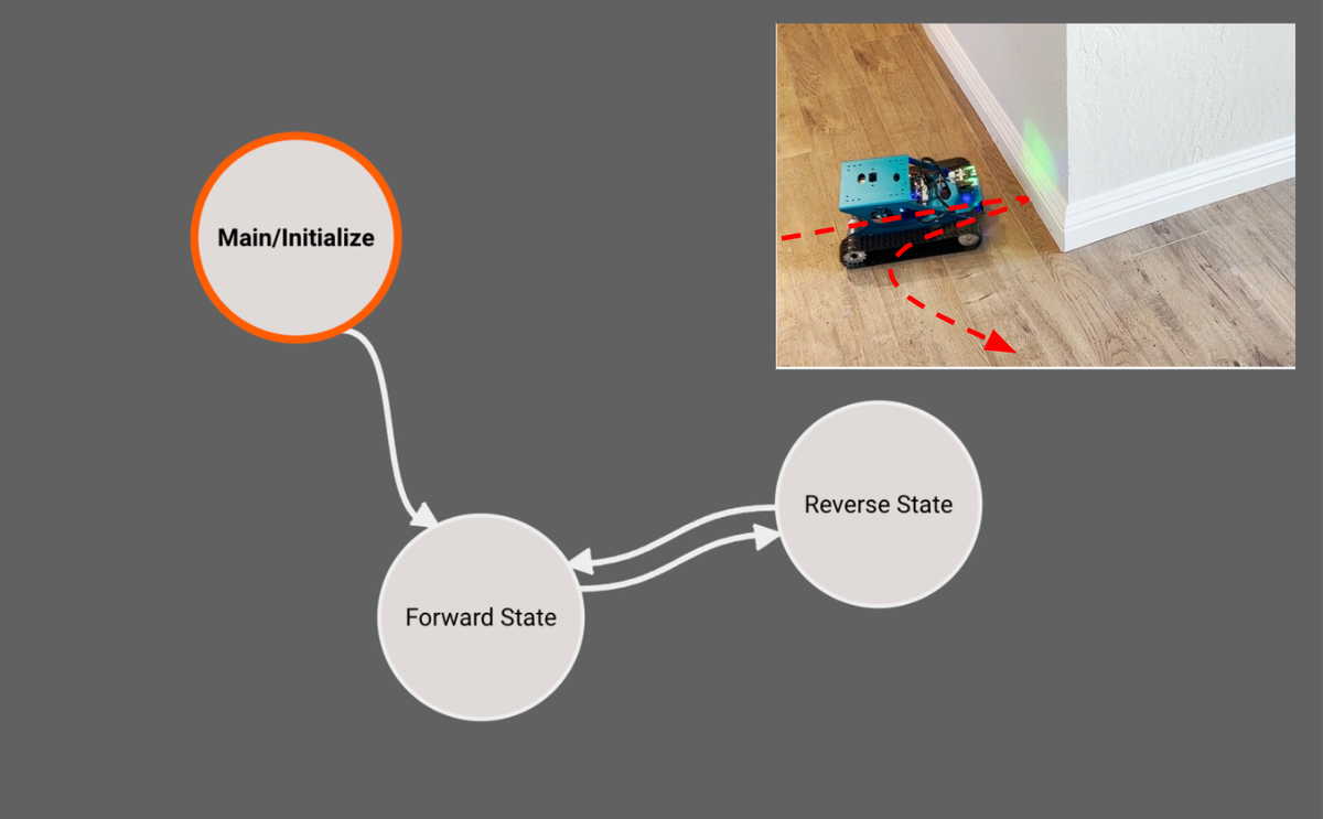
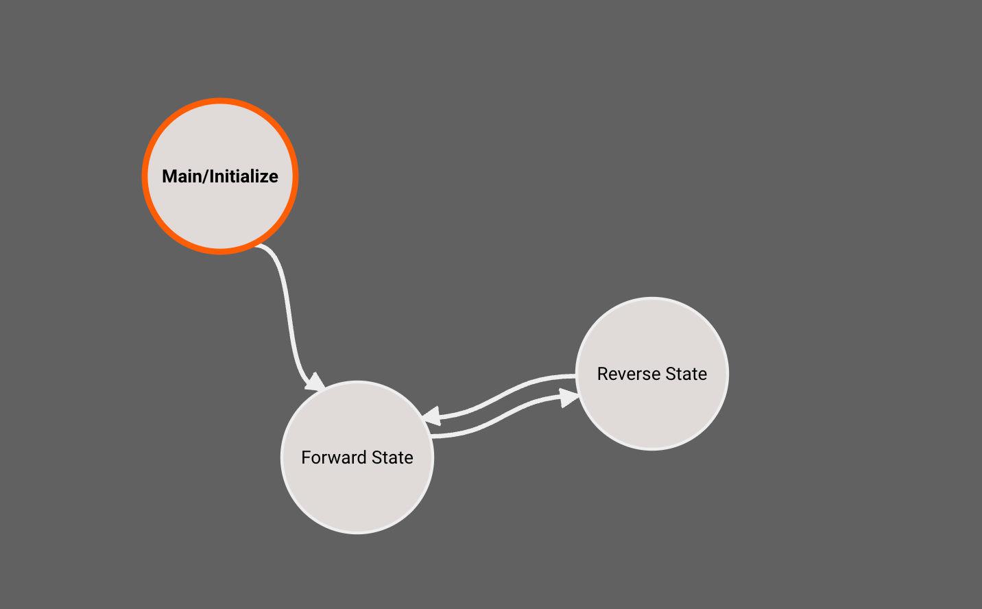
The algorithm we're implementing will follow a simple State Machine concept with three States: Initialize, Forward, and Reverse. The app will start in the Initialize state, proceed into Forward, and have the option to transition between Forward and Reverse based on whether obstacles are encountered that need to be avoided:
State Machines work by defining a set of discrete code routines (states) which the application switches between, based on some transition criteria. The rules for transitioning between states are clear, so the behavior of the robot is easier to reason about. This approach is often preferred in robotic controls over complicated If/Else logical trees, which can be difficult to wrap your head around. So, Pictorus provides a top-level State Machine for every app, which you can extend to your needs. If you don't want to use States, simply continue building your entire app in the default Main state.
Exploring the Interface and Adding States
When you open an app with multiple states, you'll first see the top-level State Machine view. Each State has its own unique block diagram that you can double-click into and edit. You can navigate back to the top-level view using breadcrumb navigation in the upper-left of the editor:
Quick note: When you create a new app, it only has one State by default: Main. You'll immediately enter that diagram when you open a new app. You can navigate up to the State Machines view and add new States by using the right-click menu:
In the example above, you'll notice that new States are initially greyed out. This is because there are a few conditions that must be met before we can generate code for a State and include it in our app:
- The State must have some valid block diagram sequences.
- The State must be reachable from the Main using StateTransition blocks.
Example: Transitioning Between States
To illustrate this, we'll add a few random blocks to New State and then connect Main -> New State using a StateTransition block. We then see New State showing up as valid a few seconds later:
Implementing the Initialize State
Lets go back to our RoomSearch app and take a look at the Main/Initialize State:
This diagram is pretty simple: It implements our Yahboom robot API from last time, and connects the range_m outport to a CompareToValue block. This block tests to see if the rangefinder reports a non-zero value (indicating it is online and scanning the room for obstacles). If this comparison block emits True, then the StateTranstion to Forward will be triggered, causing the app to leave this State on the next iteration.
Order of Operations for State Transitions
Quick note: One important feature currently lacking from the State Machine workflow in Beta is an easy means of specifying which StateTransition block should take priority if two transition blocks within the same state are both true simultaneously. Ideally, we'd like to be able to see a list of all transitions and re-order their hierarchy to our preference.
During Beta, one workaround is to add additional conditions to specify "Do this transition if some condition is True and this other condition is False. This could be achieved like so:
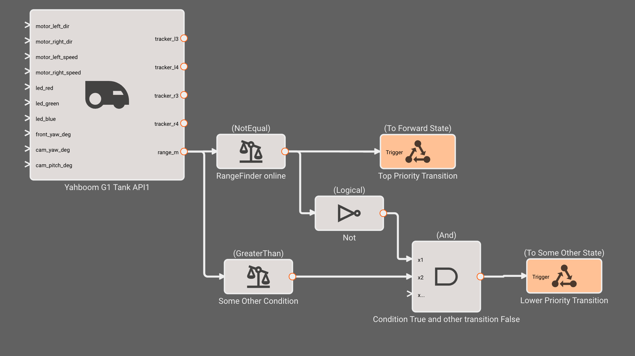
This should work fairly well for simple state machines. However, when many state transitions exist, this logic becomes cumbersome, and a better system is needed. This is a feature currently under development.
The "Maze Solving" Algorithm
The navigation approach we will implement falls under the category of Maze-Solving algorithms, a classic set of methods used for getting autonomous robots from one end of a maze to another. A surprisingly simple yet effective pattern is the Right-Hand Search rule, where the robot's movement continues forward until an obstacle is encountered; at this point, the robot always turns right before continuing onward. In doing so, it eventually works its way through complex geometries it might otherwise get stuck within. The right-hand rule approach is not bulletproof, but on the whole, it is a fairly effective way to search a space.
For our own obstacle avoidance avoiding robot, we'll use a version of this approach: Always move forward unless you see something, in which case back up, turn right, and carry on.
Commanding the ultrasonic sensor, servo motors and DC motors in Forward and Reverse States
Let's dive into our implementation, starting with the Forward State. Recall that we've entered this state once Initialize determines that our ultrasonic sensor is online and reporting range to target, so we're now ready to start driving forward.
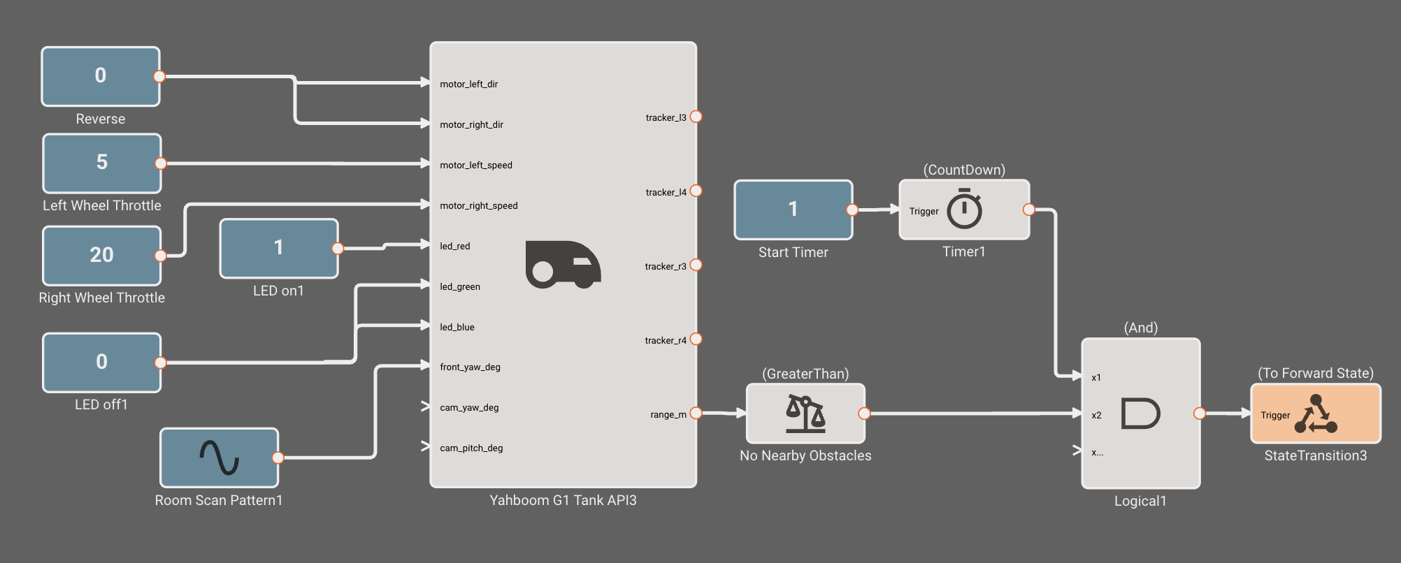
We use Constant blocks to command DC motors forward at a fixed 20% throttle. We'll send a Sinewave command to the front servo motor, causing the RangeFinder to scan the room in 60-degree sweeps. Finally, we monitors the RangeFinder output, and upon sensing an obstacle within 0.25m, trigger a StateTransition to Reverse. We don't care about the precise direction (which we could calculate from the servo motor command) of the obstacle; if anything within a 60-degree cone in front of us is detected, we'll back up.
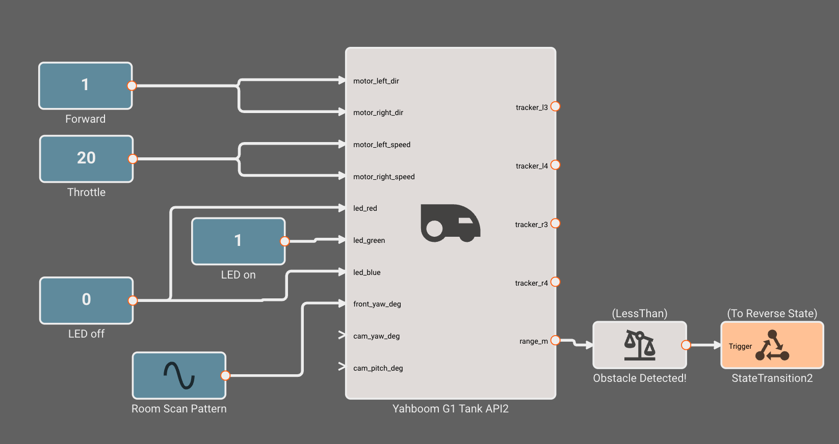
For fun, we'll also turn the green LED on, so it is clear to humans what State the robot is in. We'll use green for Forward, red for Reverse, and blue for Main. Visual cues can be especially helpful when debugging a misbehaving robot.
Next, let's talk about the Reverse State. It is slightly different from Forward. Instead of commanding equal throttle to left and right wheels, we command a differential, causing the robot to rotate counter-clockwise (when viewed from above) during the reverse maneuver. This differential maneuvering results in the robot orientation changing by at least 45 degrees, so when it completes Reverse, it will be on a new trajectory, hopefully avoiding the previously detected obstacle.
The Reverse State also implements a Timer block (with a non-interruptible countdown setting) to ensure the reverse maneuver takes place for at least 1s. After this time period, it will transition back to Forward as soon as the RangeFinder reports no obstacles within a distance of 0.35m:
Deploying the Obstacle-Avoidance Robot
With our fully instrumented State Machine, we can now set our robot loose in a room full of obstacles (refer to our earlier blog post on connecting and deploying to your device). Since our goal was to mimic the behavior of an early Roomba and thoroughly inspect the room, this basic algorithm did a surprisingly good job of visiting most sections of the space. However, if our robot's mission were to escape the room as quickly as possible, we might need a more sophisticated approach!
Hardware IO Management Across States
You might wonder: "Wait a minute, with three states, we have three API blocks implemented. Isn't this going to generate three separate software connections to the RangeFinder, motors, LEDs, and servos?"
Fortunately, the answer is no. All input and output interfaces of a Pictorus app are managed through a global IO manager, which handles all port connectivity for the app. That means when this app compiles, exactly one UDP connection to the RangeFinder is initialized. As the State Machine transitions between Initialize, Forward, and Reverse, the global IO manager grants access to a connection for the current State (and only the current State). This way, no redundant code is generated, and components within an app don't fight with each other for resource control.
Final Thoughts
Our primary goal here was to illustrate the State Machine workflow within Pictorus through a classic autonomous robot build. State machines greatly enhance the capabilities of block diagram coding, by exposing clear rules for switching between well-defined behavior modes.
You might notice some limitations with State Machines during Beta, in addition to those already mentioned. For example you can't yet specify actions to take "On Entering" or "On Exiting" a State. And sharing data across States can also be a little tricky. It currently requires the use of global data stores, which we illustrate in another robot blog post, for those curious.
Most of the limitations currently have workarounds, and we're actively developing our State Machine workflow to be more feature-complete by the time of our General Release. In the meantime, head on over to our website and give it a try! Beta is free and signup only takes a few clicks. We love all feedback, and are excited to hear what our users hope to see in the future.