'Hello World!' - Controlling LEDs with Pictorus
In this post we'll run through the customary "Hello World" exercise in electronics - controlling LEDs via software.
In this post we'll run through the customary "Hello World" exercise in electronics - controlling LEDs via software. We'll set up the control software in a Pictorus app and deploy it to a Raspberry Pi 4.
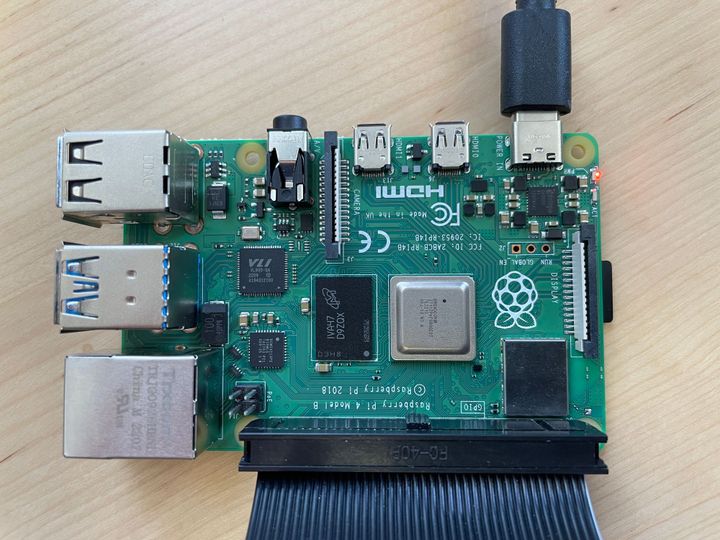
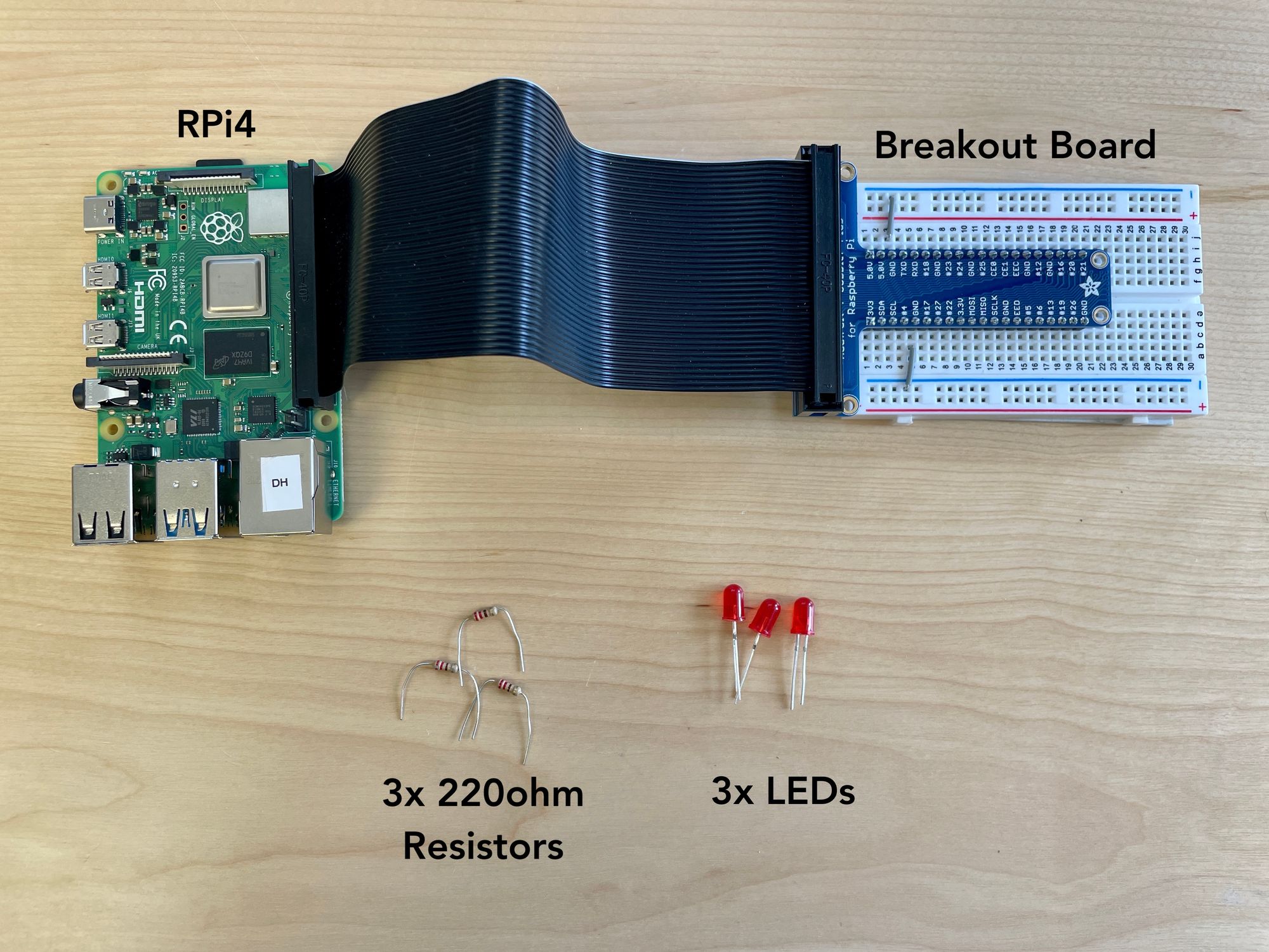
Here's a snapshot of the components we'll be using:
We'll start by creating a new app, and dragging blocks into the main (default) state. As a first step, we'll make a single LED blink using a Squarewave generator block and GpioOutput block. Here, we can adjust the on/off duration in the Squarewave settings in order to make the LED blink faster or more slowly.
Generating an LED blinking output in Pictorus
LED blink with Squarewave output block
The GpioOutput block only generates a HIGH or LOW signal (check out our documentation for reference on this block and others). In order to create a dimming effect, we can introduce pulse-width modulation with a Pwm output block. We can assign the same output pin to this block, set it at a high enough frequency (e.g. 400Hz) to avoid visible flickering, and have a duty cycle set at the desired brightness (0-1).
Dimming and LED with a Pwm output block
To create a fading effect, we can attach a Sinewave generator to the duty cycle input of the Pwm block, setting the bias at 0.5 and amplitude to 0.5 (creating a wave that oscillates between 0 and 1). We can adjust the frequency of this Sinewave to change the rate at which we increase or decrease the LED brightness.
Using a Sinewave block to create an LED fade in<>fade out effect.
LED dimming with Sinewave generator and Pwm output blocks
Finally, to create the ripple effect shown at the top of this blog post, we wire up two other LED (with resistors) to numbered GPIO pins on our breadboard. In Pictorus, we copy-paste the same three LED control blocks, assigning each Pwm output to the correct pin. We also alter the phase of the second and third sine waves, offsetting their sweeps up<>down in brightness to create the ripple effect.
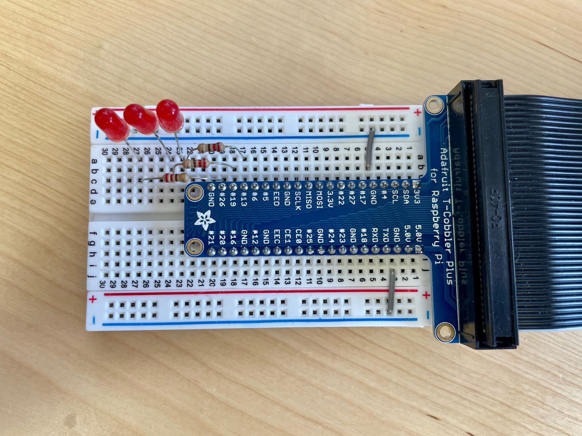
Setting up the three-LED ripple sequence
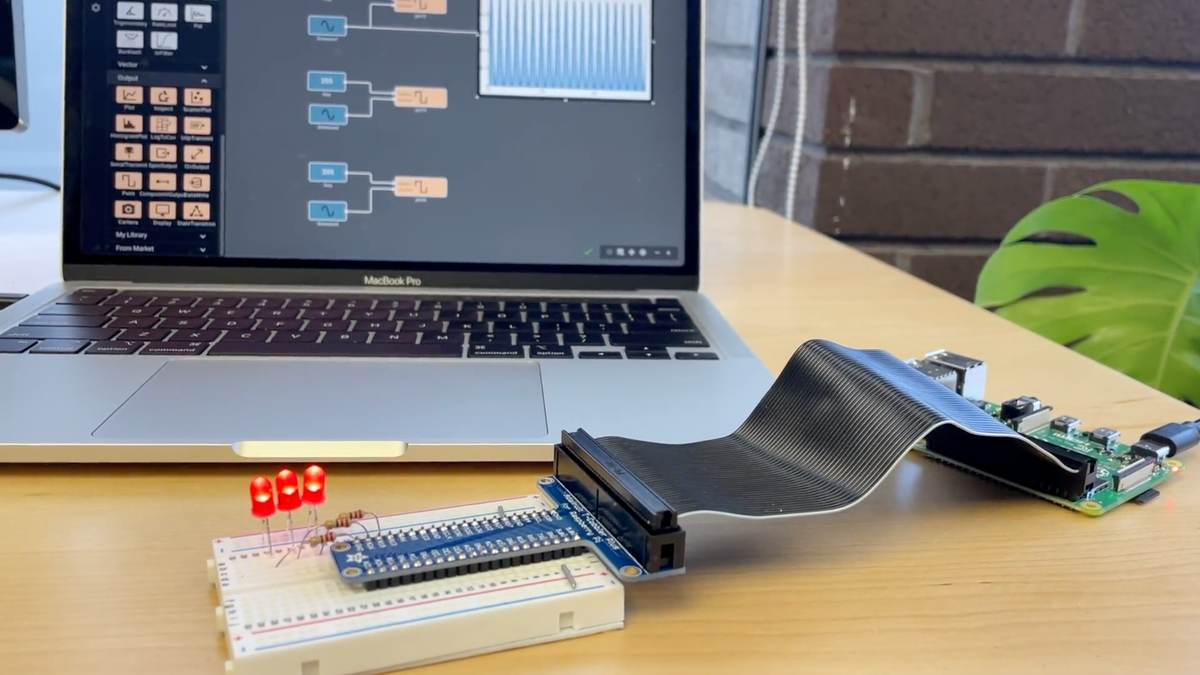
Here it is in action!
3-LED ripple
We hope this was a smooth intro to the Pictorus interface and working with a couple of basic output and generator blocks. Check out our other blog posts, such as building a robotic software API and an obstacle-avoiding robot, to learn about other Pictorus features!