Building a robotic software API using Pictorus
To illustrate creating a new component from scratch, we're going to use the Yahboom G1 Tank as our hardware platform. The component we build here will be available on the public marketplace (for free), so you can incorporate it into your own Yahboom projects.
Code reusability is a bedrock principle in software engineering. We want to always be thinking about ways to wrap functionality into reusable components that will make our lives easier, and our code more maintainable.
In Pictorus, we have the concept of Components, which are custom blocks users can create, composed of other blocks under the hood. By making components reusable, we add them to our library so they can be used in any application we develop in the future. This is essentially publishing an API, either for yourself, your team, or the larger community.
Components can contain other components, enabling powerful abstractions. Components shared to the public marketplace allow users to build upon what others have done.
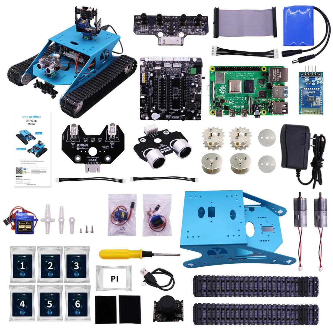
To illustrate creating a new component from scratch, we're going to use the Yahboom G1 Tank as our hardware platform. This relatively affordable, sturdy robot comes with a myriad of sensors and actuators, and we'd like to build a component once which we can reuse in future apps. The component we build here will be available on the public marketplace (for free), so you can incorporate it into your own Yahboom projects.
Yahboom G1 Tank Overview
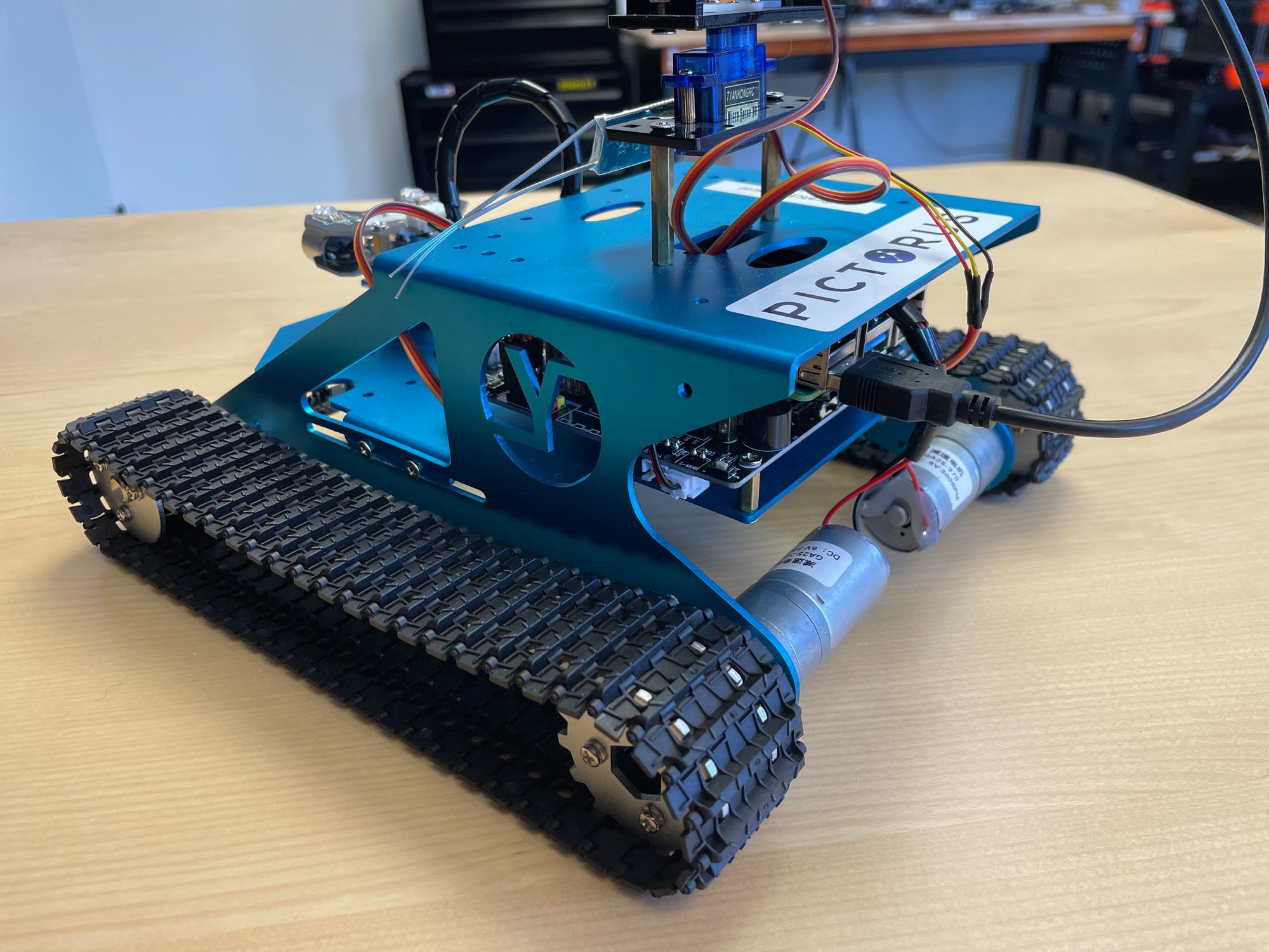
The Yahboom G1 Tank is a great entry-level robotics platform. You can buy them from Amazon relatively cheaply, they take an hour or two to assemble, they're not made entirely of cheap plastic, and best of all, they ship with a single board computer (Jetson or Rasberry Pi) we can sync to Pictorus!
There are a handful of actuators to control, and a few sensors to read from. To move, we can command two brushed DC motors forward or backwards, driving four wheels via a continuous track (tank treads).
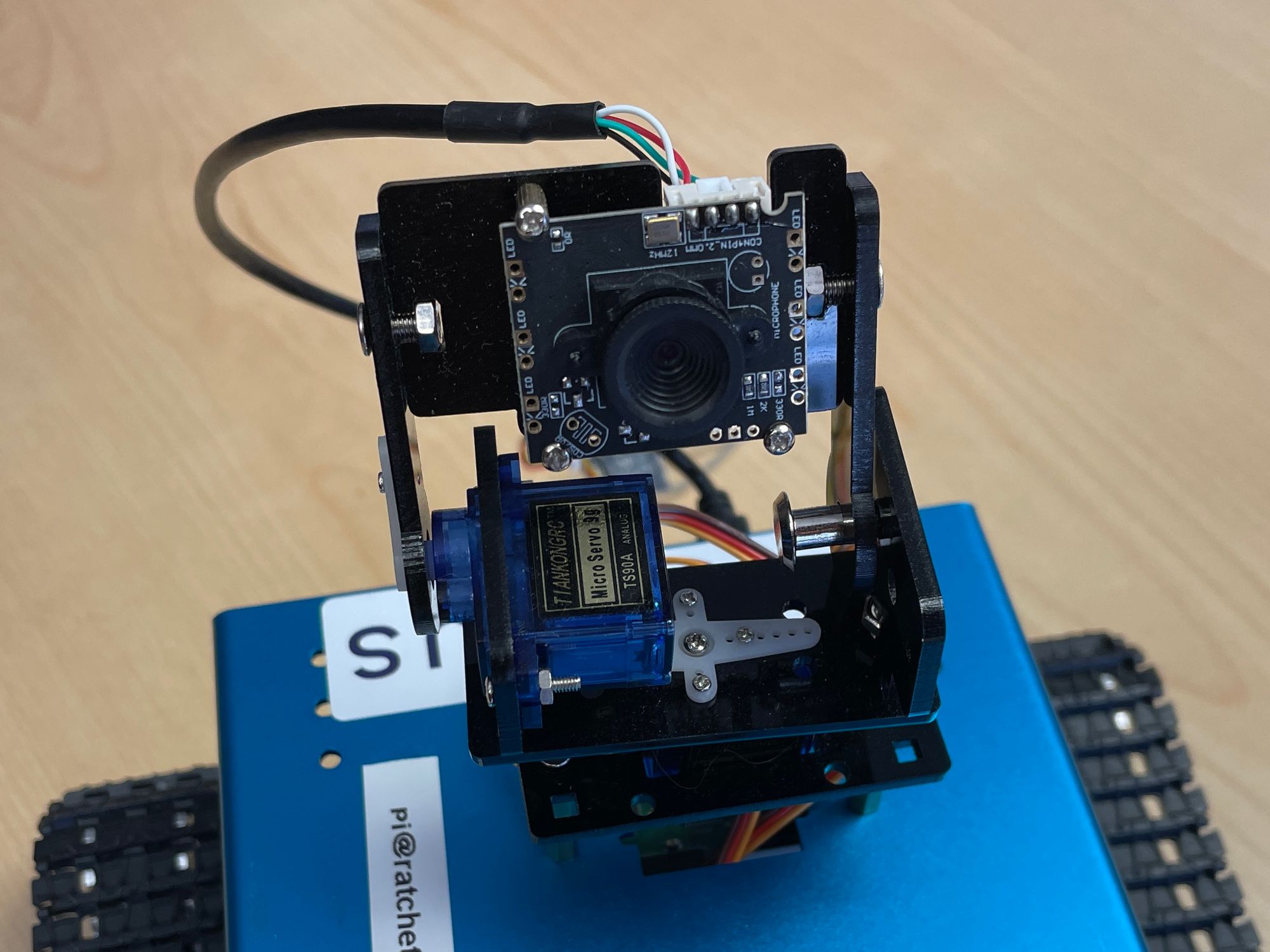
We can also articulate 3 different servo motors, two of which adjust yaw and pitch of a simple camera, and the third adjusting yaw of an ultrasonic range finder and some LEDs. We can turn on red, green, and blue lights within the LEDs, or combine them to create other colors.
For sensors, we have the range finder, which we can command with pings to estimate distances to nearby objects. This is a pretty involved sensor, so we dedicated an entire blog post to it.
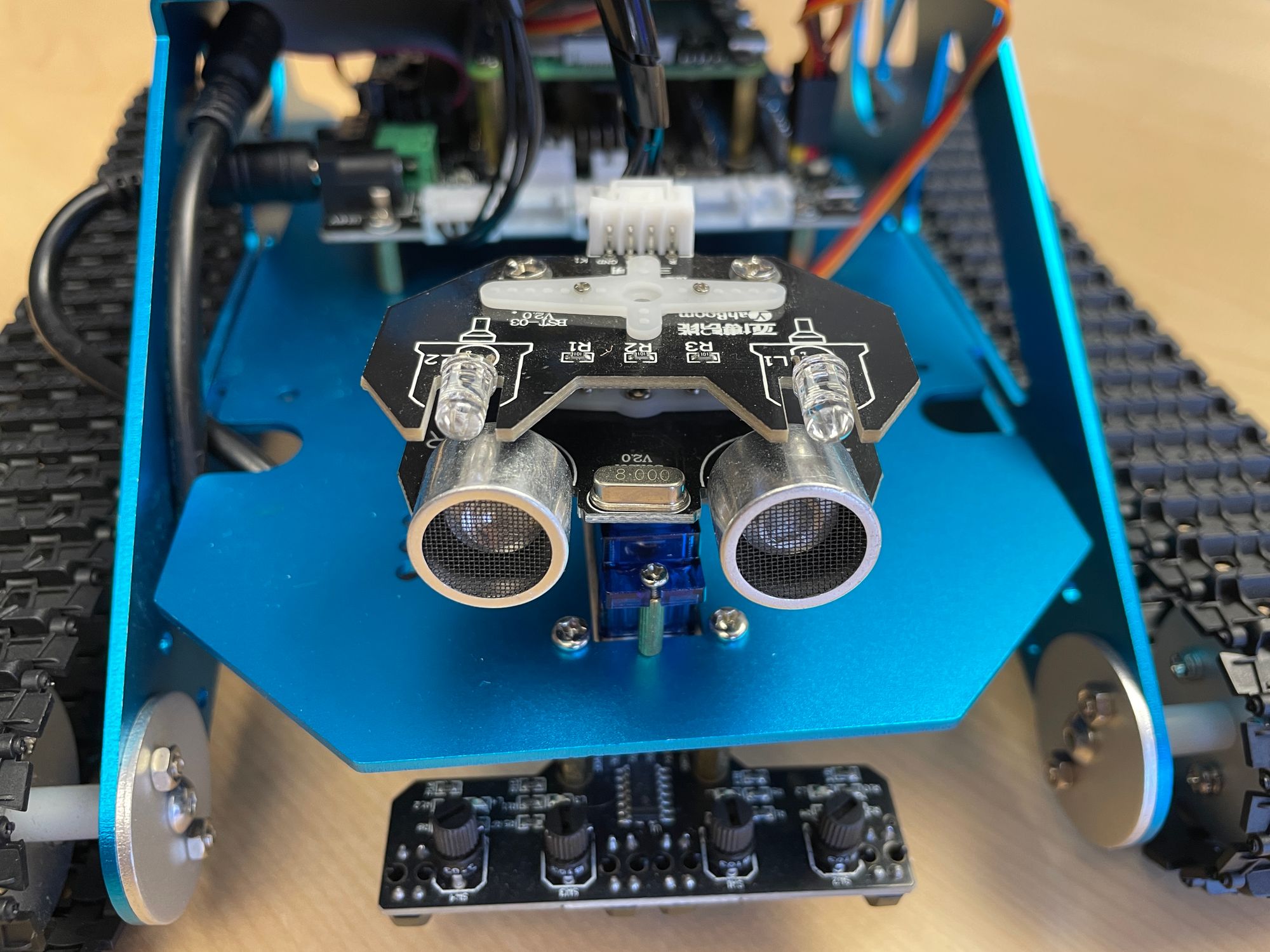
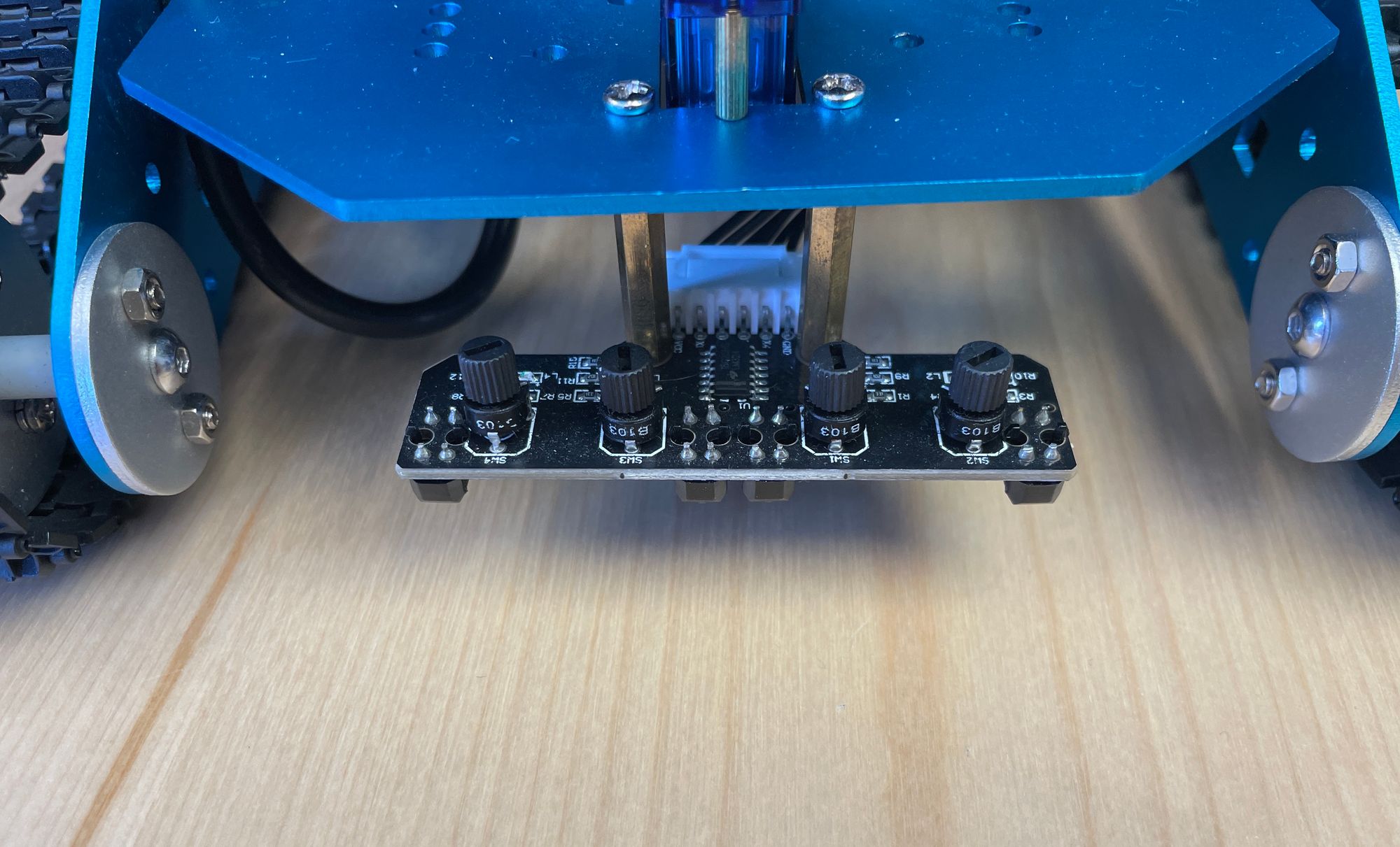
We also have 4 downward-facing contrast sensors mounted to the front of the tank. These go high or low based on whether a dark or light surface is beneath, allowing us to do things like track a black line path on a white background.
In the following sections, we'll go through each device, building up sub-components for each, which we'll then wrap into one top-level API. We'll then build a simple app to control the robot.
LED Component
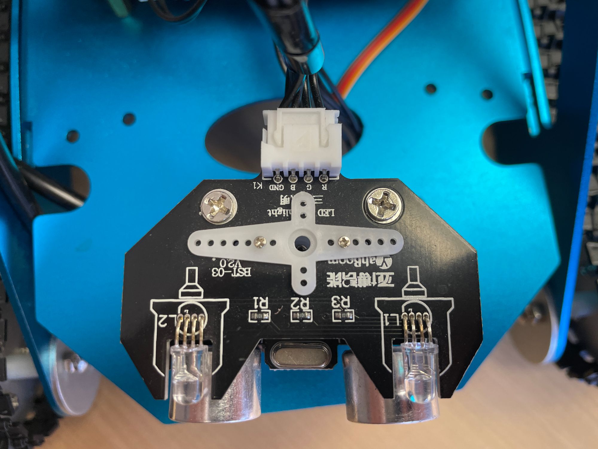
The LEDs are controlled pretty easily with GPIO pins. We can turn red, green, and blue pins on or off this way. The spec sheet shows us the following pinout for the Pi (Jetson may be different):
- Red: Pin 22
- Green: Pin 27
- Blue: Pin 24
To start building this component, we right click on the canvas and select New Component

Components have some special properties, including that you can give them custom variables scoped to all blocks contained within. When developing an API, we should consider which variables we want to expose to the user at the top level. In this case, we'll make the GPIO pin numbers custom variables. This will allow users to tweak the pin numbers from this top level view if they need to, without needing to understand how the component works under the hood.
Create new custom variables by right-clicking on the component and selecting Settings. We can then add a new variable for each pin:
We'll come back to these variables later, when we set up the GPIO blocks.
Next, let's create the inputs to this component. Since we want users to control each pin separately, we create three Component Inputs from within the LED Component:
Now the last step is to connect these inputs to the GPIO Output blocks they'll drive. For each GPIO block, we go to the block settings, and assign the pin number from the custom variables we defined earlier:
Notice that for each block, we had the option to either manually specify the pin number, or instead reference a variable.
Okay, now we have a component to test! In earlier blog posts we showed how to sync a device with Pictorus cloud, so now we can connect to the Yahboom G1 and try turning on the LEDs! We also showed how to drive an LED with a squarewave signal, which we'll repeat here to blink the LEDs at different frequencies for each color:
Now we connect to the tank, deploy the app, and see what the LEDs do:
Servo Component
Servo control is only slightly more complicated. They're driven via Pulse Width Modulation (PWM), and can articulate 180 degrees.
The PWM Output block helps us here. In addition to specifying the PWM pin number, we also need to send a constant command frequency (50Hz, specified by this device's manufacturer), and then allow users to command the desired angle, which our component will map to the PWM duty cycle. For these particular servos, the conversion from commanded degrees to duty cycle is (2.5 + degrees * 10 / 180)*0.01, which we can easily implement using a SymPy block, which allows calculations from simple pythonic syntax:
Now that we have a servo component, it's really easy to copy and paste it several times, to create one servo controller for each of the three servos on the Yahboom. All we need to do is change the pin number!
We can now connect to our robot, and send it commands from 0 -> 180 degrees with a Sinewave generator block. We give the sinewave an amplitude of 90 degrees, and a bias of 90 degrees, in order to get the sweep we want:
Motor Component
The two brushed DC motors we can command combine the functionality we've used thus far:
- PWM Block to command motor speed
- Two GPIO pins to command direction (forward / reverse)
For the PWM, these motors require a frequency of 255 hertz, and a duty cycle from 0 to 1 for 0-100% throttle:
For the GPIO pins, we command them in differential. So for forward, we command pin A to be 1, while pin B is 0. For reverse, we command pin A to 0 and pin B to 1. This differential strategy is common in electronics for robustness and to mitigate electrical interference effects. We can use a Not block to the input signal to achieve this:
Now we can copy paste to create separate left and right motor controllers, and experiment with driving around:
Line Tracker Component
The Line tracker component is really simple. We just read 4 GPIO pins (pins 3, 4, 5, and 18 for our board). The pins should be high by default, and go low when detecting a color change. Somewhat counter-intuitively, this means the pin will read zero when the LED on the sensor is on. Since there's only one line tracker on this robot, we won't bother parameterizing the pin numbers:
Connecting to our robot and plotting the output, we should be able to see the pins going low as we move a hand under the tracker sensors:
Range finder Component
As mentioned earlier, the ultrasonic range finder is quite a bit more complicated than the other components. This is because we have to run it at 10,000 hertz, and perform some math and logic to process sensor readings. We've dedicated a full blog post to the implementation here.
For our API, we don't want to embed this component directly. That would require running the entire app at 10,000hz, which is way overkill for most use cases. Instead, as we demonstrated in this blog post, we'll assume that the range finder has been setup to run as a standalone app on our device, and is broadcasting range estimates over UDP at 10hz. This way, all our API needs to do is listen to that UDP port to publish range estimates.
As our prior post described, our standalone range finder app is looking for a "keep alive" signal, which tells it to keep estimating range and broadcasting measurements because some consumer app is requesting them. Absent any keep alive pings, the rangefinder app goes into hibernation, so it isn't pinging incessantly.
We can implement this keep alive signal easily by broadcasting a square wave to the expected UDP port. So long as the app containing this API is running, the periodic square wave pulse will keep the range finder app broadcasting:
Now we can subscribe to the range estimate with a UDP Receive block. Data from sensors always arrives as bytes, so we introduce a Json Load block to deserialize, which by default simply attempts to convert bytes to a numeric value:
To test this Component, we'll push this software to the robot, and ensure that our Rangefinder app is also running in another process. We can wave our hand in front of the rangefinder and get distance estimates from the new component:
Publishing the final API
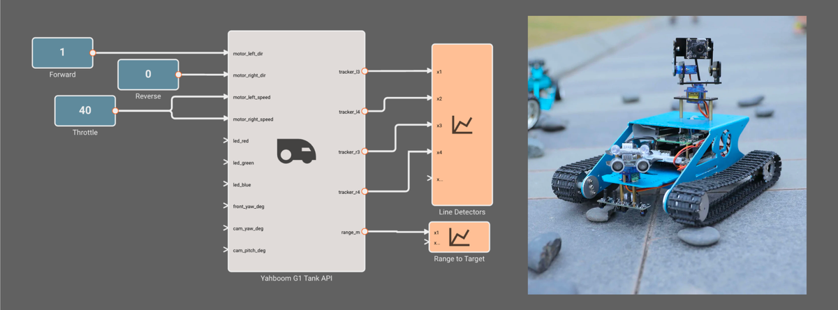
Now that we'll built and tested each sub-component of this API, it's time to pull them altogether into our final component, and make it re-usable in other apps. Here's the final component:
We can see all the actuators we can command show up as left-side inputs to the API, and all the sensors we can read data from show up as right-side outputs from the API.
Finally, let's publish this component so we can re-use it later. We right-click the component and select "Make Re-usable". This opens a prompt that lets us input some specifics about the component. When we click save, we notice the component now shows up in our "My Library" section, so we can drag and drop it!
Final Thoughts
Components are a powerful way to create re-usable functionality to share across your apps. Hopefully this introduction helps get you acquainted.
You may have noticed the "Publish to Marketplace" option, which we did not check. We're currently building out marketplace features, so far Beta users will not be able to publish their components publicly. But you will be able to access all the pre-built components from these blog posts under the "From Market" block tab.